How to Use 4ch 3.3V 5V 12V 24V Digital Logic Level Converter Module Optical Isolation: Examples, Pinouts, and Specs
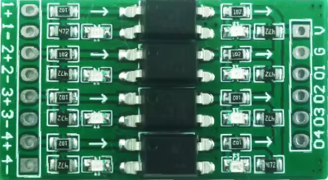
4ch 3.3V 5V 12V 24V Digital Logic Level Converter Module with Optical Isolation
Introduction
The 4-channel Digital Logic Level Converter Module with Optical Isolation is a versatile and reliable component designed for interfacing devices operating at different voltage levels. It enables bidirectional voltage level shifting between 3.3V, 5V, 12V, and 24V logic levels, making it an essential tool for projects involving microcontrollers, sensors, and industrial equipment. The module's optical isolation feature provides robust protection against voltage spikes, noise, and ground loops, ensuring the safety of sensitive components and improving signal integrity.
Common Applications
- Interfacing microcontrollers (e.g., Arduino, Raspberry Pi) with higher voltage devices.
- Industrial automation systems requiring isolation between control and power circuits.
- Communication between devices with different logic levels in IoT and embedded systems.
- Protecting sensitive components from electrical noise and voltage transients.
Technical Specifications
The following table outlines the key technical details of the 4ch Digital Logic Level Converter Module:
| Parameter | Specification |
|---|---|
| Operating Voltage (Low) | 3.3V or 5V |
| Operating Voltage (High) | 12V or 24V |
| Channels | 4 (bidirectional) |
| Isolation Type | Optical Isolation |
| Maximum Current per Channel | 20mA |
| Signal Direction | Bidirectional |
| Operating Temperature | -40°C to 85°C |
| Dimensions | 50mm x 30mm x 15mm |
Pin Configuration and Descriptions
| Pin Name | Description |
|---|---|
| VCC_L | Low voltage power supply input (3.3V or 5V). |
| VCC_H | High voltage power supply input (12V or 24V). |
| GND | Ground connection (common for both low and high voltage sides). |
| IN1, IN2, IN3, IN4 | Input pins for low voltage signals (connected to microcontroller or device). |
| OUT1, OUT2, OUT3, OUT4 | Output pins for high voltage signals (connected to high voltage device). |
Usage Instructions
How to Use the Module in a Circuit
Power Connections:
- Connect the low voltage power supply (3.3V or 5V) to the
VCC_Lpin. - Connect the high voltage power supply (12V or 24V) to the
VCC_Hpin. - Connect the
GNDpin to the ground of both power supplies.
- Connect the low voltage power supply (3.3V or 5V) to the
Signal Connections:
- Connect the low voltage signal lines (e.g., from a microcontroller) to the
IN1,IN2,IN3, andIN4pins. - Connect the high voltage signal lines (e.g., to a motor driver or industrial device) to the corresponding
OUT1,OUT2,OUT3, andOUT4pins.
- Connect the low voltage signal lines (e.g., from a microcontroller) to the
Bidirectional Communication:
- The module supports bidirectional communication, so signals can flow in either direction between the low and high voltage sides.
Optical Isolation:
- The optical isolation ensures that the low voltage and high voltage sides are electrically isolated, protecting sensitive components from voltage spikes and noise.
Important Considerations and Best Practices
- Ensure that the power supply voltages for
VCC_LandVCC_Hare within the specified ranges. - Do not exceed the maximum current rating of 20mA per channel.
- Use decoupling capacitors near the power supply pins to reduce noise and improve stability.
- Verify the ground connection between the module and the devices it interfaces with.
- Avoid exposing the module to extreme temperatures or humidity.
Example: Interfacing with an Arduino UNO
The following example demonstrates how to use the module to interface an Arduino UNO (operating at 5V) with a 24V industrial device.
Circuit Diagram
- Connect the Arduino's
5Vpin to the module'sVCC_Lpin. - Connect the Arduino's
GNDpin to the module'sGNDpin. - Connect a 24V power supply to the module's
VCC_Hpin. - Connect the Arduino's digital output pin (e.g.,
D2) to the module'sIN1pin. - Connect the module's
OUT1pin to the input of the 24V device.
Arduino Code Example
// Example code for using the 4ch Digital Logic Level Converter Module
// This code toggles a 24V device ON and OFF using an Arduino UNO.

const int controlPin = 2; // Arduino pin connected to IN1 on the module

void setup() {
  pinMode(controlPin, OUTPUT); // Set the control pin as an output
}

void loop() {
  digitalWrite(controlPin, HIGH); // Turn the 24V device ON
  delay(1000);                    // Wait for 1 second
  digitalWrite(controlPin, LOW);  // Turn the 24V device OFF
  delay(1000);                    // Wait for 1 second
}
Troubleshooting and FAQs
Common Issues and Solutions
| Issue | Possible Cause | Solution |
|---|---|---|
| No output signal on the high voltage side | Incorrect power supply connections | Verify that VCC_L and VCC_H are connected to the correct voltage levels. |
| Signal distortion or noise | Insufficient decoupling or noisy environment | Add decoupling capacitors near the power supply pins. |
| Module overheating | Exceeding current rating | Ensure the current per channel does not exceed 20mA. |
| No communication between devices | Ground not properly connected | Ensure a common ground connection between the module and connected devices. |
FAQs
Can I use this module for unidirectional signals?
- Yes, the module works for both unidirectional and bidirectional signals.
What happens if I connect the wrong voltage to
VCC_LorVCC_H?- Connecting incorrect voltages may damage the module. Always double-check the power supply connections.
Can I use this module with a Raspberry Pi?
- Yes, the module is compatible with Raspberry Pi and other 3.3V logic devices.
Is the optical isolation bidirectional?
- Yes, the optical isolation works for bidirectional signals, ensuring safety and signal integrity.
Conclusion
The 4ch 3.3V 5V 12V 24V Digital Logic Level Converter Module with Optical Isolation is a powerful and versatile tool for interfacing devices with different logic levels. Its optical isolation feature ensures robust protection for sensitive components, making it ideal for a wide range of applications in embedded systems, industrial automation, and IoT projects. By following the usage instructions and best practices outlined in this documentation, you can effectively integrate this module into your projects and ensure reliable performance.
Explore Projects Built with 4ch 3.3V 5V 12V 24V Digital Logic Level Converter Module Optical Isolation


Explore Projects Built with 4ch 3.3V 5V 12V 24V Digital Logic Level Converter Module Optical Isolation