
How to Use Stepper motor - NEMA-17: Examples, Pinouts, and Specs
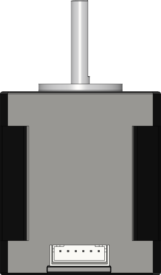
 Design with Stepper motor - NEMA-17 in Cirkit Designer
Introduction
The NEMA-17 stepper motor is a type of electric motor that divides a full rotation into a large number of discrete steps. This allows for precise control of position, speed, and acceleration, making it ideal for applications requiring high accuracy. The "NEMA-17" designation refers to the motor's faceplate dimensions, which measure 1.7 x 1.7 inches (43.2 x 43.2 mm).
Explore Projects Built with Stepper motor - NEMA-17
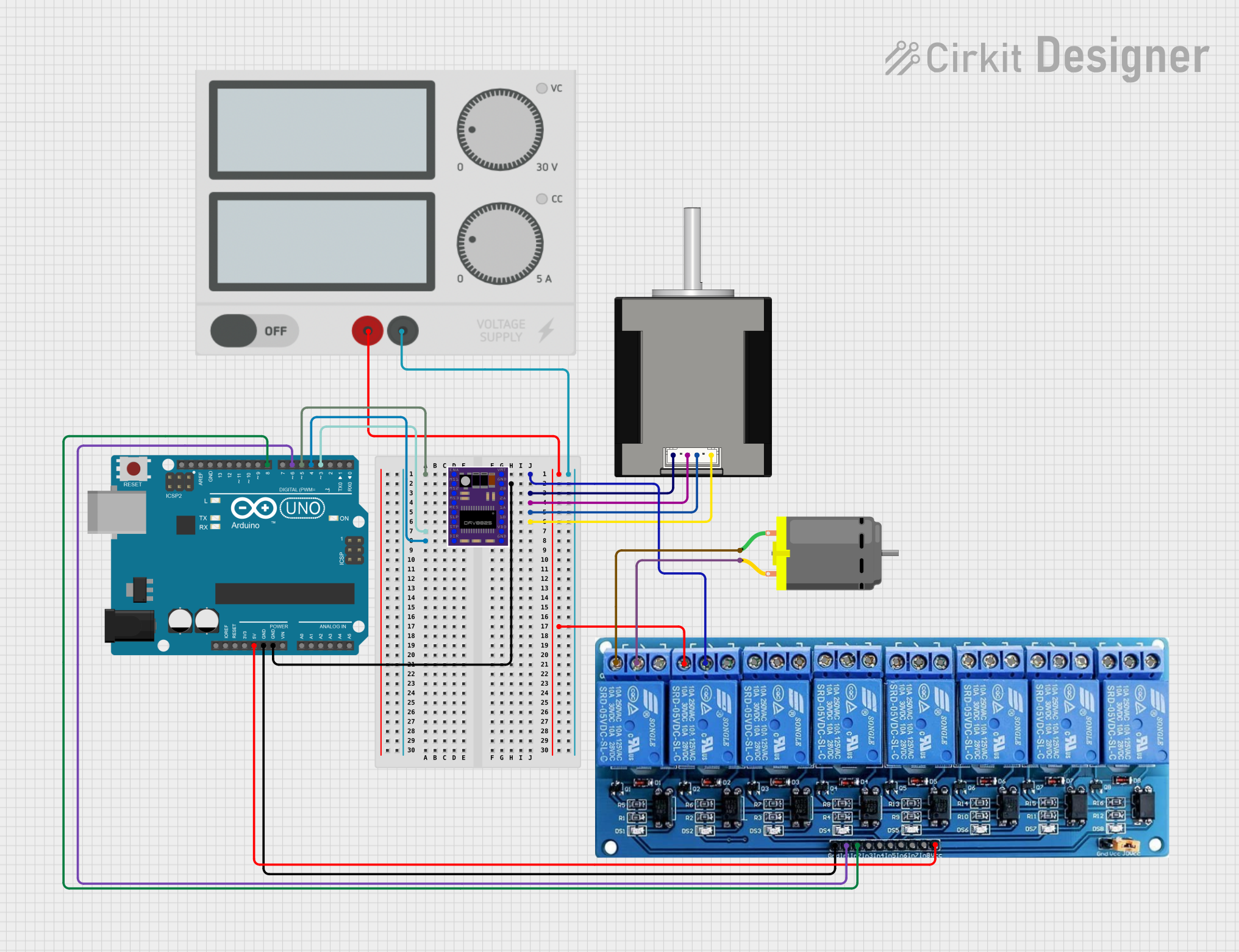 Open Project in Cirkit Designer
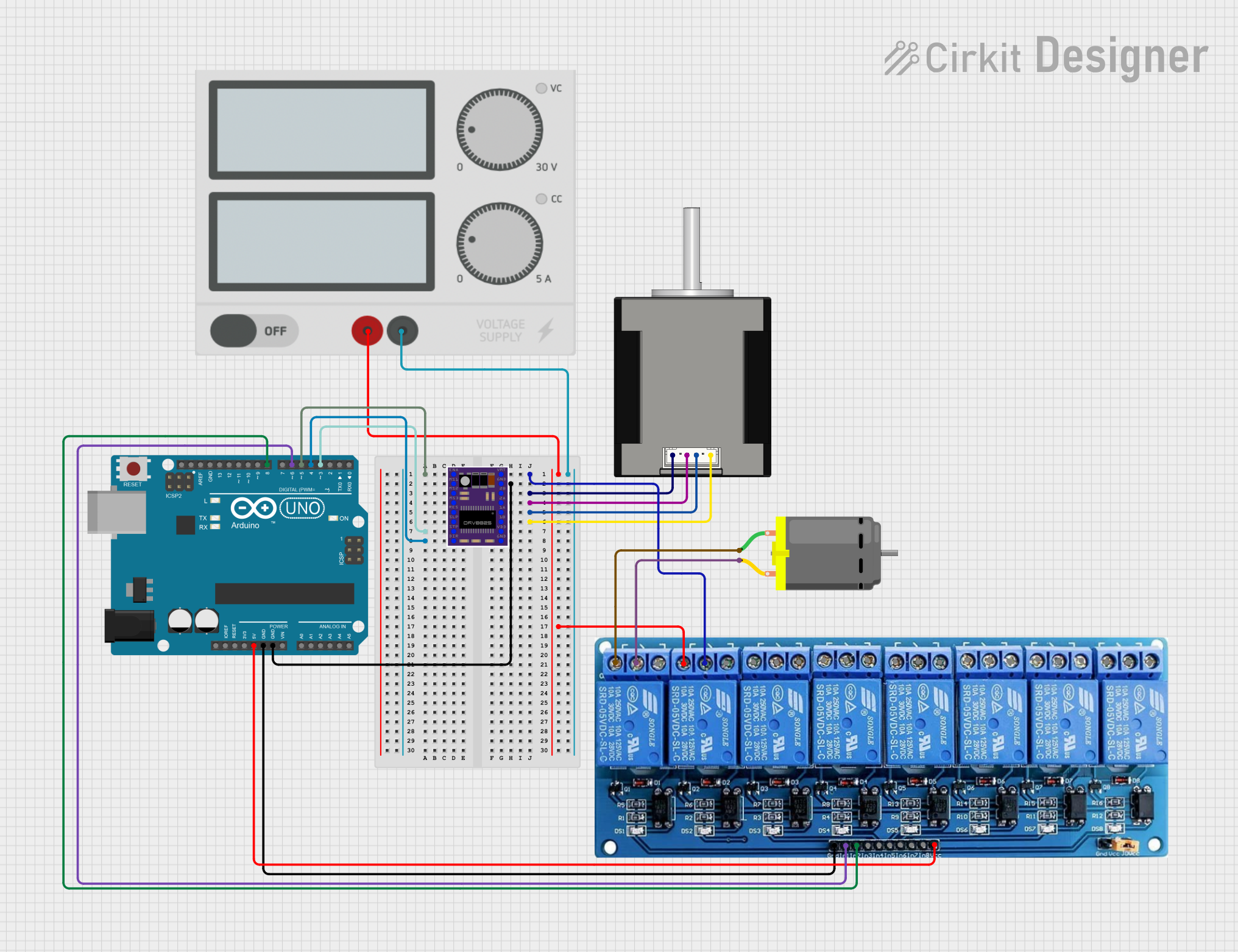 Open Project in Cirkit Designer
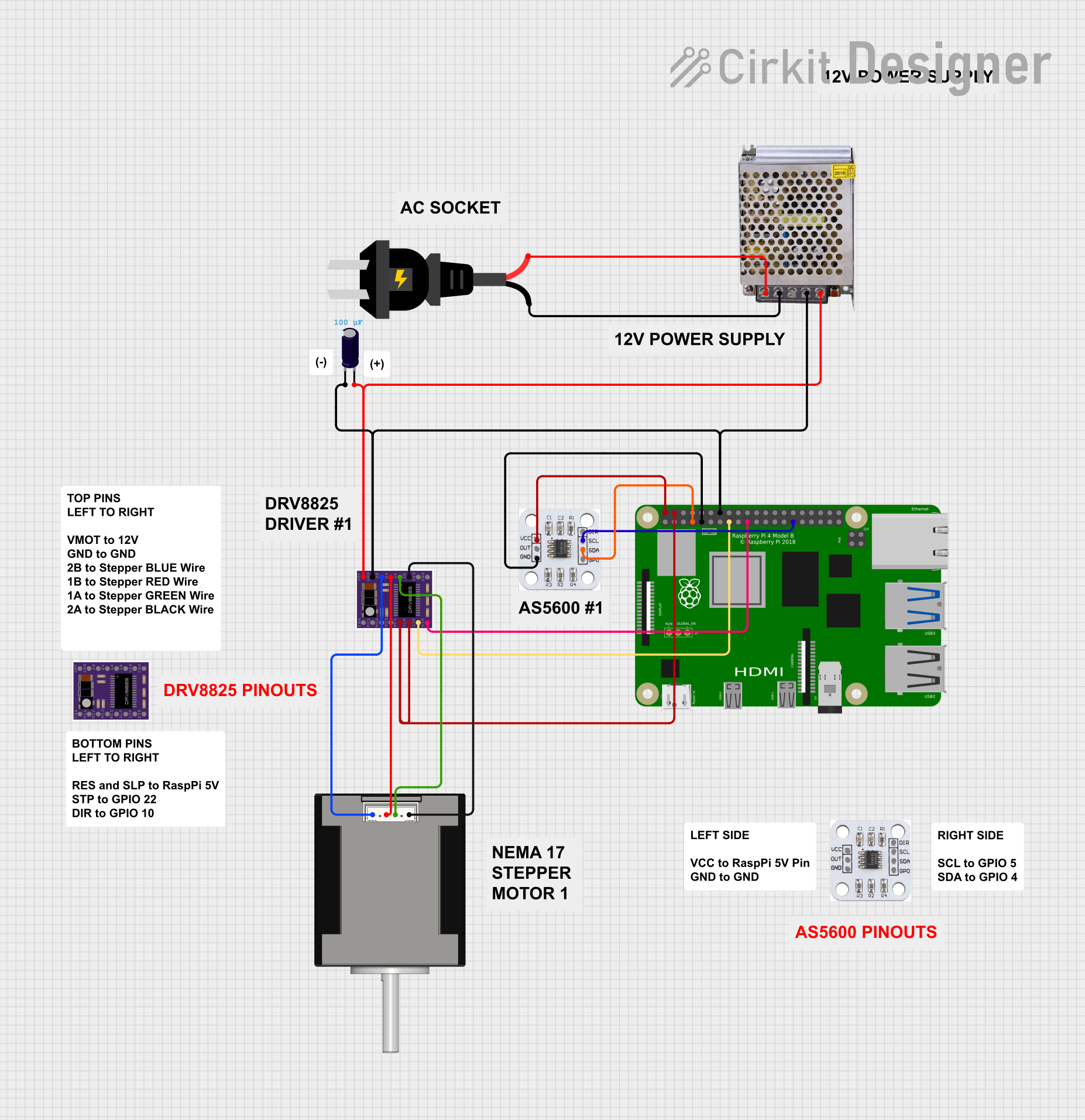 Open Project in Cirkit Designer
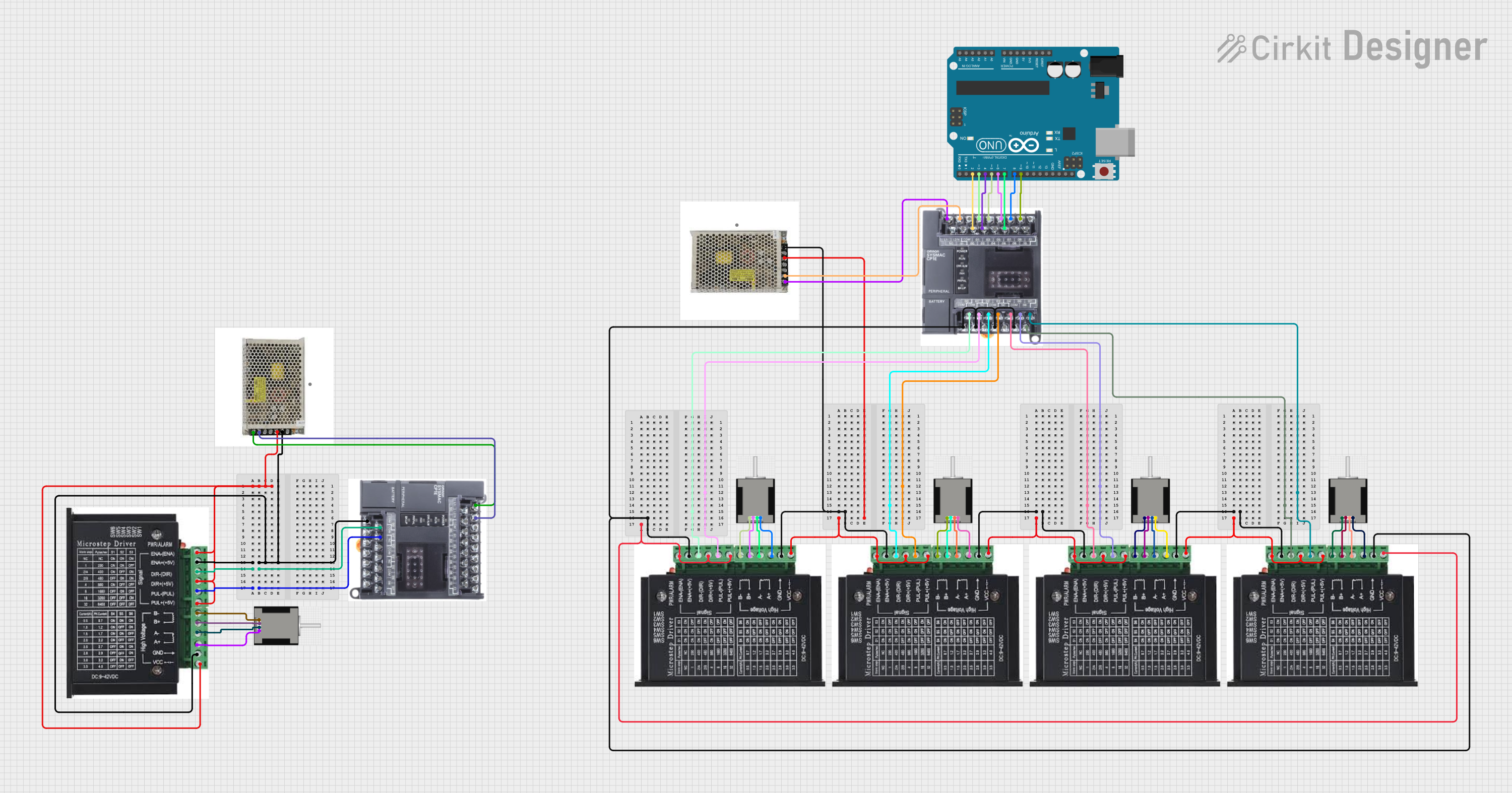 Open Project in Cirkit Designer
Explore Projects Built with Stepper motor - NEMA-17
Open Project in Cirkit DesignerOpen Project in Cirkit DesignerOpen Project in Cirkit DesignerOpen Project in Cirkit DesignerCommon Applications and Use Cases
- 3D printers
- CNC machines
- Robotics
- Camera sliders
- Automated conveyor systems
- Precision positioning systems
Technical Specifications
Below are the key technical details for a typical NEMA-17 stepper motor. Note that specific models may vary slightly, so always refer to the datasheet for your particular motor.
| Parameter | Value |
|---|---|
| Step Angle | 1.8° (200 steps per revolution) |
| Holding Torque | 3.5 kg-cm (varies by model) |
| Rated Voltage | 12V (common range: 3-12V) |
| Rated Current | 1.2A per phase (varies by model) |
| Resistance per Phase | 10 ohms (typical) |
| Inductance per Phase | 2.8 mH (typical) |
| Shaft Diameter | 5 mm |
| Dimensions (L x W x H) | 42 x 42 x 48 mm (varies by model) |
| Weight | ~280 g |
Pin Configuration and Descriptions
The NEMA-17 stepper motor typically has four wires for bipolar operation. The wire colors and their corresponding coil connections are as follows:
| Wire Color | Coil | Description |
|---|---|---|
| Red | A+ | Positive terminal of Coil A |
| Blue | A- | Negative terminal of Coil A |
| Green | B+ | Positive terminal of Coil B |
| Black | B- | Negative terminal of Coil B |
Note: Always verify the wire colors and connections with the motor's datasheet, as they may vary between manufacturers.
Usage Instructions
How to Use the NEMA-17 in a Circuit
- Power Supply: Ensure the motor is powered by a suitable power supply. A 12V DC power source is commonly used, but check the motor's rated voltage and current.
- Driver Module: Use a stepper motor driver (e.g., A4988 or DRV8825) to control the motor. These drivers regulate current and simplify step control.
- Microcontroller: Connect the driver module to a microcontroller (e.g., Arduino UNO) to send step and direction signals.
- Wiring: Connect the motor's wires to the driver module as per the pin configuration. Ensure proper coil pairing (A+ with A-, B+ with B-).
- Programming: Write a program to control the motor's steps, speed, and direction.
Important Considerations and Best Practices
- Current Limiting: Set the current limit on the driver module to prevent overheating or damage to the motor.
- Heat Management: Stepper motors can get hot during operation. Ensure proper ventilation or heat dissipation.
- Step Resolution: Use microstepping (if supported by the driver) for smoother motion and higher precision.
- Power Down: Avoid leaving the motor powered when idle for extended periods to reduce heat and energy consumption.
Example Code for Arduino UNO
Below is an example of how to control a NEMA-17 stepper motor using an A4988 driver and an Arduino UNO:
// Define pin connections
#define STEP_PIN 3  // Pin connected to the STEP input of the driver
#define DIR_PIN 4   // Pin connected to the DIR input of the driver

void setup() {
  pinMode(STEP_PIN, OUTPUT); // Set STEP pin as output
  pinMode(DIR_PIN, OUTPUT);  // Set DIR pin as output

  digitalWrite(DIR_PIN, HIGH); // Set initial direction (HIGH = clockwise)
}

void loop() {
  // Rotate the motor one full revolution (200 steps for 1.8° step angle)
  for (int i = 0; i < 200; i++) {
    digitalWrite(STEP_PIN, HIGH); // Generate a step pulse
    delayMicroseconds(1000);      // Wait 1 ms (adjust for speed control)
    digitalWrite(STEP_PIN, LOW);  // End the step pulse
    delayMicroseconds(1000);      // Wait 1 ms before the next step
  }

  delay(1000); // Pause for 1 second before changing direction

  // Change direction
  digitalWrite(DIR_PIN, LOW); // Set direction to counterclockwise
  delay(1000); // Pause for 1 second before starting the next revolution
}
Note: Adjust the delay values in the code to control the motor's speed. Shorter delays result in faster rotation.
Troubleshooting and FAQs
Common Issues and Solutions
Motor Not Moving
- Cause: Incorrect wiring or loose connections.
- Solution: Double-check the wiring and ensure proper coil pairing.
Motor Vibrates but Doesn't Rotate
- Cause: Incorrect step sequence or insufficient current.
- Solution: Verify the driver settings and ensure the current limit is properly configured.
Motor Overheating
- Cause: Excessive current or prolonged operation.
- Solution: Reduce the current limit on the driver and ensure proper ventilation.
Skipping Steps
- Cause: Excessive load or insufficient torque.
- Solution: Reduce the load or use a motor with higher torque.
Driver Overheating
- Cause: High current or inadequate cooling.
- Solution: Add a heatsink or cooling fan to the driver module.
FAQs
Q: Can I run the NEMA-17 without a driver module?
A: No, a driver module is required to control the motor's steps and regulate current.Q: What is microstepping, and why is it useful?
A: Microstepping divides each full step into smaller steps, resulting in smoother motion and higher precision.Q: Can I power the motor directly from the Arduino?
A: No, the Arduino cannot supply enough current. Use an external power supply and a driver module.Q: How do I determine the correct coil pairs?
A: Use a multimeter to measure resistance. The two wires with the lowest resistance form a coil pair.
By following this documentation, you can effectively integrate and operate the NEMA-17 stepper motor in your projects.