How to Use 15P UMNL II PLUG-FRONT: Examples, Pinouts, and Specs
Introduction
The 15P UMNL II PLUG-FRONT (Manufacturer Part ID: 94VO-770043-1) is a 15-pin universal male connector designed for front panel mounting. Manufactured by MATE-N-LOK, this connector is widely used in electronic systems to establish secure and reliable electrical connections. Its robust design ensures durability and consistent performance, making it suitable for a variety of applications.
Explore Projects Built with 15P UMNL II PLUG-FRONT


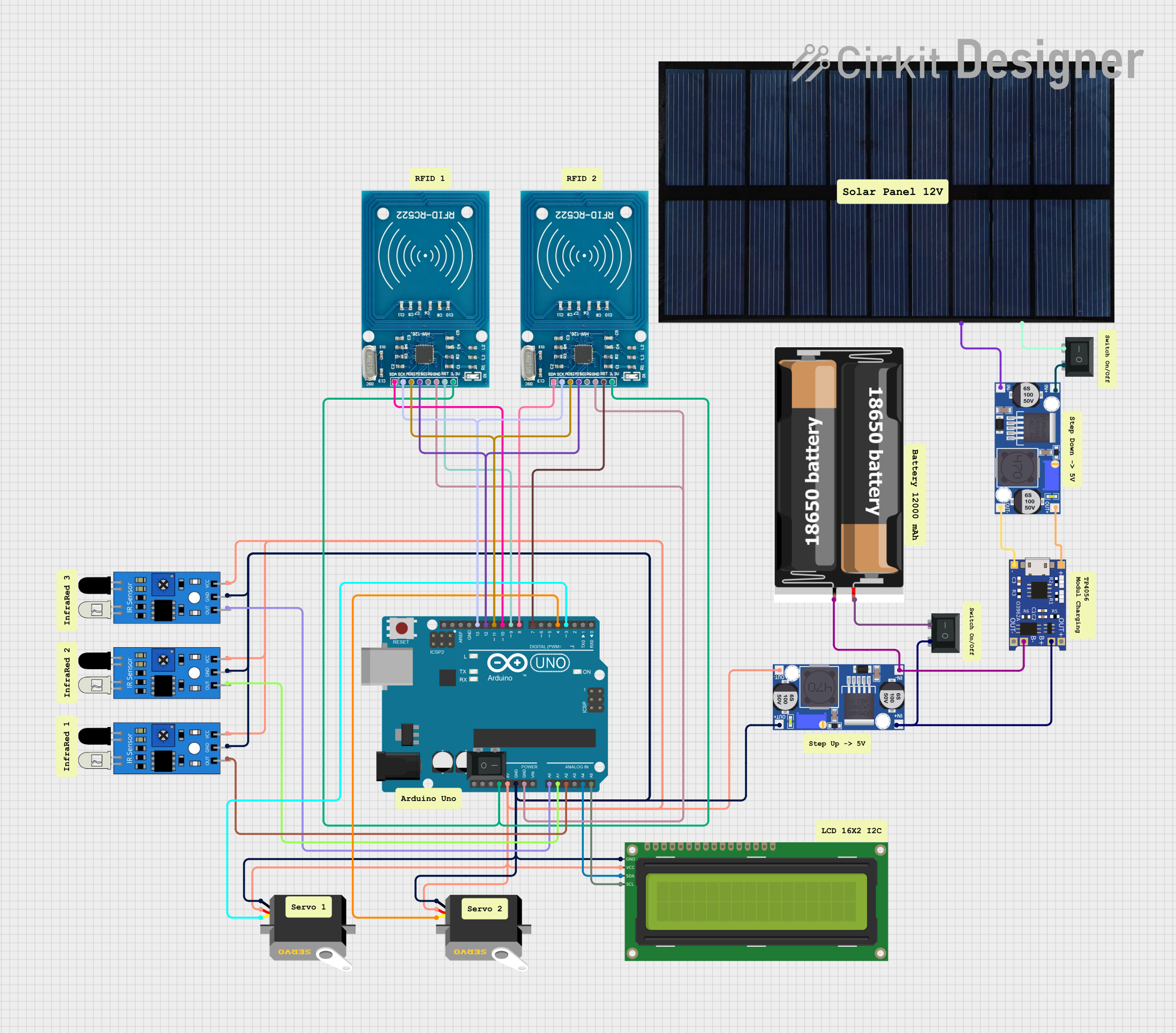
Explore Projects Built with 15P UMNL II PLUG-FRONT
Common Applications and Use Cases
- Power distribution in electronic devices
- Signal transmission in industrial equipment
- Automotive wiring harnesses
- Consumer electronics and appliances
- Prototyping and custom PCB designs
Technical Specifications
Key Technical Details
| Parameter | Value |
|---|---|
| Manufacturer | MATE-N-LOK |
| Part ID | 94VO-770043-1 |
| Number of Pins | 15 |
| Mounting Style | Front panel |
| Connector Type | Male |
| Material | UL 94V-0 rated thermoplastic |
| Current Rating | Up to 15A per pin |
| Voltage Rating | 600V AC/DC |
| Operating Temperature | -55°C to +105°C |
| Contact Plating | Tin |
| Wire Gauge Compatibility | 24 AWG to 18 AWG |
Pin Configuration and Descriptions
The 15P UMNL II PLUG-FRONT features 15 pins arranged in a single row. Below is the pinout description:
| Pin Number | Description | Typical Use Case |
|---|---|---|
| 1 | Ground (GND) | Common ground connection |
| 2 | Power Supply (+V) | Positive voltage input |
| 3-14 | Signal/Power Lines | Customizable per design |
| 15 | Shield/Chassis Ground | EMI shielding |
Note: Pins 3-14 are versatile and can be used for signal transmission or additional power lines, depending on the application.
Usage Instructions
How to Use the Component in a Circuit
Mounting the Connector:
- Secure the connector to the front panel using screws or a snap-fit mechanism.
- Ensure proper alignment to avoid stress on the pins.
Wiring:
- Strip the wires to the appropriate length (as per the datasheet).
- Crimp the wires to the corresponding contacts using a compatible crimping tool.
- Insert the crimped wires into the connector housing until they click into place.
Mating:
- Align the male connector with the corresponding female connector.
- Push the connectors together until they lock securely.
Testing:
- Verify continuity and ensure there are no loose connections.
- Test the circuit under load to confirm proper operation.
Important Considerations and Best Practices
- Wire Selection: Use wires within the specified gauge range (24 AWG to 18 AWG) to ensure proper fit and electrical performance.
- Contact Cleaning: Periodically clean the contacts to prevent oxidation and maintain reliable connections.
- Avoid Overloading: Do not exceed the current and voltage ratings to prevent overheating or damage.
- Secure Mounting: Ensure the connector is firmly mounted to avoid mechanical stress on the pins.
Example: Connecting to an Arduino UNO
The 15P UMNL II PLUG-FRONT can be used to interface external devices with an Arduino UNO. Below is an example of connecting a sensor to the Arduino using this connector:
Circuit Diagram
- Pin 1: Ground (GND) → Arduino GND
- Pin 2: Power Supply (+5V) → Arduino 5V
- Pin 3: Signal Line → Arduino Digital Pin 2
Arduino Code Example
// Example code for reading a digital signal from a sensor connected via the
// 15P UMNL II PLUG-FRONT connector to an Arduino UNO.

const int sensorPin = 2; // Pin 3 of the connector is wired to Digital Pin 2
int sensorValue = 0;     // Variable to store the sensor reading

void setup() {
  pinMode(sensorPin, INPUT); // Set the sensor pin as an input
  Serial.begin(9600);        // Initialize serial communication
}

void loop() {
  sensorValue = digitalRead(sensorPin); // Read the sensor value
  Serial.print("Sensor Value: ");
  Serial.println(sensorValue);          // Print the sensor value to the Serial Monitor
  delay(500);                           // Wait for 500ms before the next reading
}
Note: Ensure proper grounding and shielding to minimize noise in signal lines.
Troubleshooting and FAQs
Common Issues and Solutions
| Issue | Possible Cause | Solution |
|---|---|---|
| Loose connections | Improper crimping or insertion | Re-crimp the wires and reinsert |
| Overheating of pins | Exceeding current/voltage ratings | Reduce load or use thicker wires |
| Signal interference | Poor grounding or shielding | Connect Pin 15 to chassis ground |
| Connector not locking properly | Misalignment during mating | Realign and ensure proper fit |
FAQs
Can this connector handle high-frequency signals?
- Yes, but ensure proper shielding and grounding to minimize interference.
What tools are required for crimping?
- Use a compatible crimping tool recommended by the manufacturer for best results.
Is this connector waterproof?
- No, the 15P UMNL II PLUG-FRONT is not rated for waterproof applications. Use additional sealing methods if required.
Can I use this connector for DC and AC applications?
- Yes, it supports both DC and AC applications up to 600V.
By following this documentation, users can effectively integrate the 15P UMNL II PLUG-FRONT into their projects and ensure reliable performance.