Cirkit Designer
Your all-in-one circuit design IDE
Home /
Component Documentation
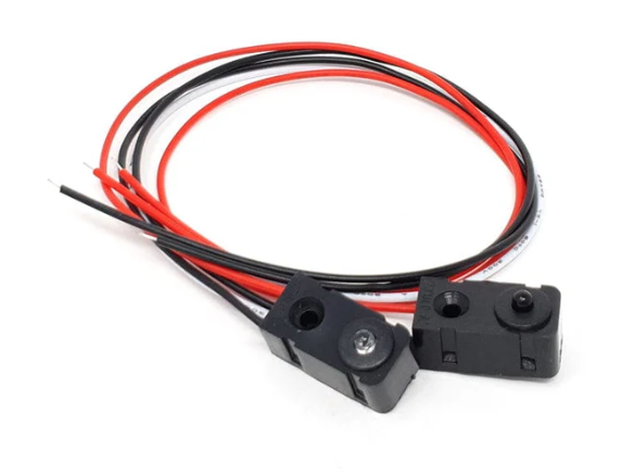
How to Use IR Beam Break Sensor: Examples, Pinouts, and Specs
Introduction
An IR (Infrared) beam break sensor is an electronic device that detects the presence or absence of an object based on the interruption of an infrared light beam. The sensor consists of an infrared emitter and a receiver. When an object passes between the emitter and receiver, the beam is broken, and the sensor outputs a signal indicating the event. This type of sensor is commonly used in applications such as security systems, manufacturing line item counting, and user input for electronics.
Explore Projects Built with IR Beam Break Sensor
Arduino-Based IR Break Beam Sensor with I2C LCD Display
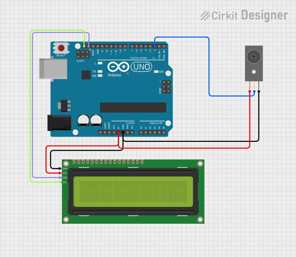
This circuit utilizes an Arduino UNO to monitor an IR Break Beam Sensor, which detects interruptions in a beam. When the beam is intact, the system displays 'Beam Intact' on a 16x2 I2C LCD, and when the beam is broken, it updates the display to show 'Beam Broken'. The circuit is designed for real-time monitoring of the beam status, providing immediate visual feedback.
ESP32-Based Security System with RFID and Laser Tripwire

This circuit is designed for a comprehensive security and access control system with motion detection, access via RFID, and a break-beam sensor. It includes a solenoid lock controlled by a relay, visual and audible alerts, and a robust power management system with solar and battery backup to ensure uninterrupted operation.
Battery-Powered IR Sensor Alarm with LED Indicator and Buzzer
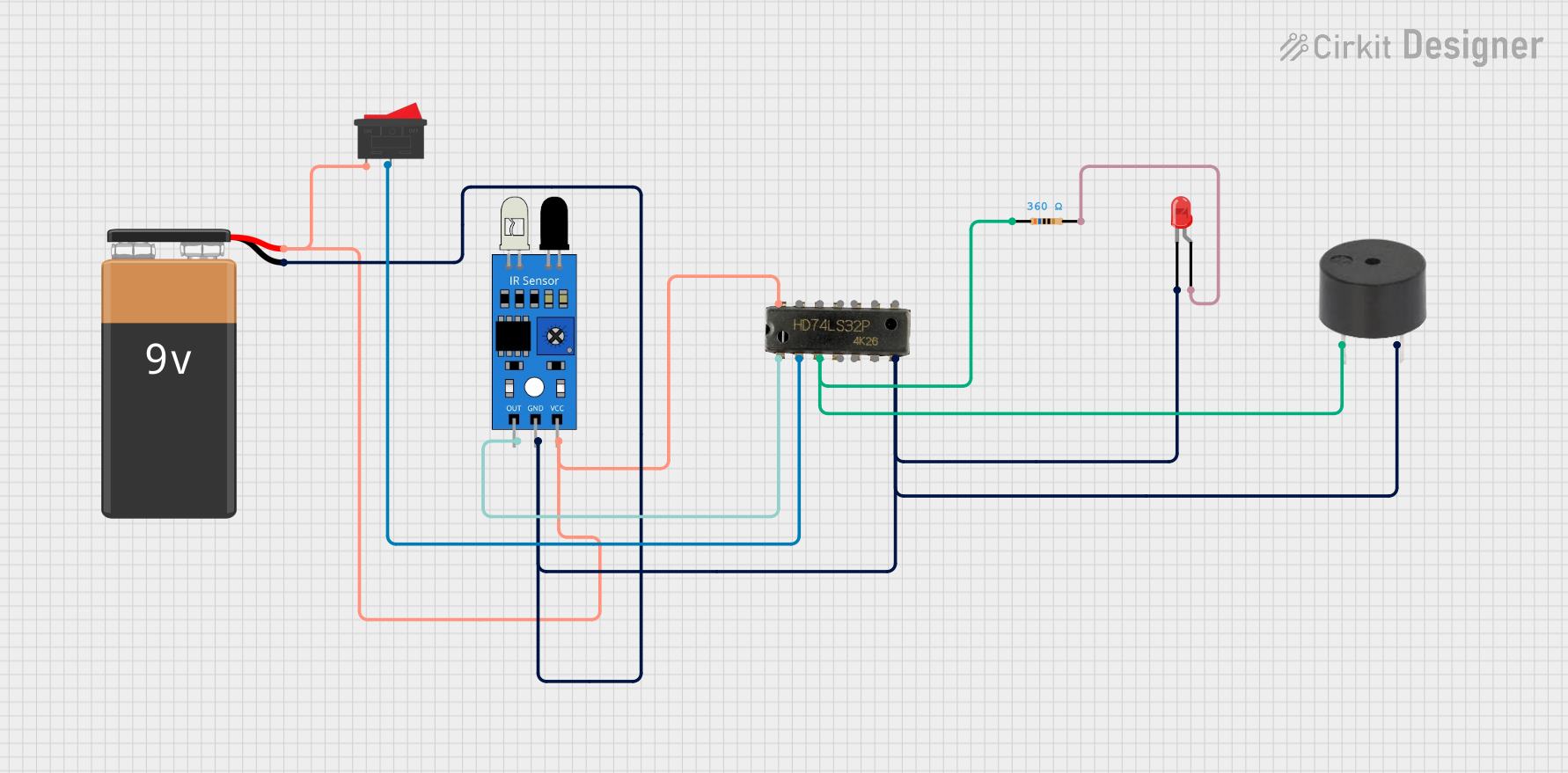
This circuit is a simple IR sensor-based alarm system. When the IR sensor detects an object, it triggers an OR gate, which in turn activates a buzzer and lights up an LED. The circuit is powered by a 9V battery and includes a rocker switch to control the power supply.
IR Sensor-Based Voltage Regulator with Visual Indicators
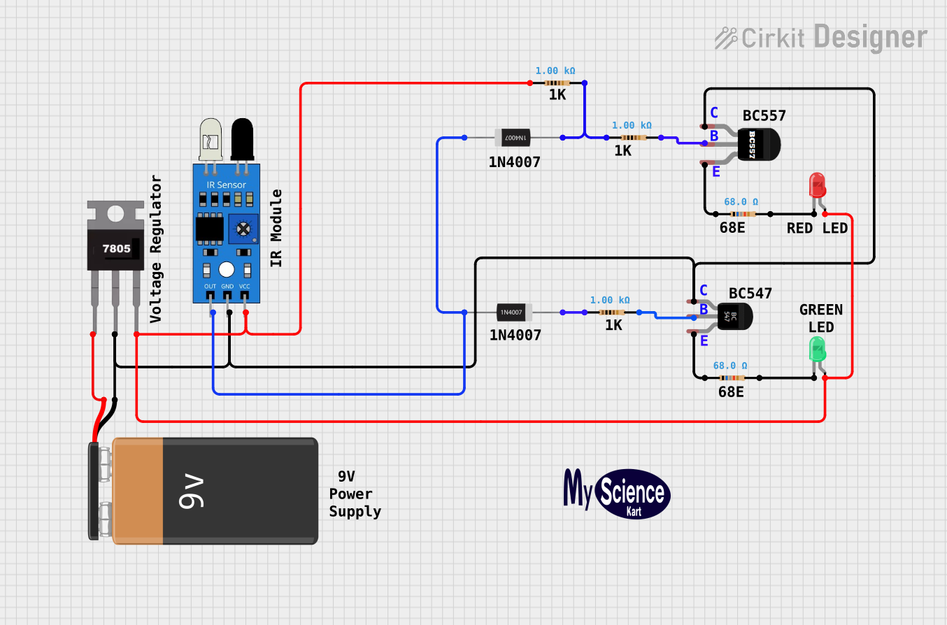
This circuit appears to be a sensor-based system that uses an IR sensor to detect the presence of an object or motion. When the IR sensor output is active, it likely triggers a change in the state of the LEDs, possibly indicating detection status with a red or green LED. The 9V battery powers the circuit, with a 7805 voltage regulator providing a stable 5V supply to the IR sensor and LEDs, while BC547 and BC557 transistors may be used to amplify the sensor signal or drive the LEDs. Diodes and resistors are used for protection and current limiting respectively.
Explore Projects Built with IR Beam Break Sensor
Arduino-Based IR Break Beam Sensor with I2C LCD Display
This circuit utilizes an Arduino UNO to monitor an IR Break Beam Sensor, which detects interruptions in a beam. When the beam is intact, the system displays 'Beam Intact' on a 16x2 I2C LCD, and when the beam is broken, it updates the display to show 'Beam Broken'. The circuit is designed for real-time monitoring of the beam status, providing immediate visual feedback.
ESP32-Based Security System with RFID and Laser Tripwire
This circuit is designed for a comprehensive security and access control system with motion detection, access via RFID, and a break-beam sensor. It includes a solenoid lock controlled by a relay, visual and audible alerts, and a robust power management system with solar and battery backup to ensure uninterrupted operation.
Battery-Powered IR Sensor Alarm with LED Indicator and Buzzer
This circuit is a simple IR sensor-based alarm system. When the IR sensor detects an object, it triggers an OR gate, which in turn activates a buzzer and lights up an LED. The circuit is powered by a 9V battery and includes a rocker switch to control the power supply.
IR Sensor-Based Voltage Regulator with Visual Indicators
This circuit appears to be a sensor-based system that uses an IR sensor to detect the presence of an object or motion. When the IR sensor output is active, it likely triggers a change in the state of the LEDs, possibly indicating detection status with a red or green LED. The 9V battery powers the circuit, with a 7805 voltage regulator providing a stable 5V supply to the IR sensor and LEDs, while BC547 and BC557 transistors may be used to amplify the sensor signal or drive the LEDs. Diodes and resistors are used for protection and current limiting respectively.
Common Applications and Use Cases
- Intruder detection in security systems
- Item counting on conveyor belts
- Elevator door safety systems
- User input for interactive installations
Technical Specifications
Key Technical Details
- Operating Voltage: 3.3V to 5V
- Current Consumption: 10mA (typical)
- Output Type: Digital signal (High when beam is unbroken, Low when beam is broken)
- Wavelength: 940nm (infrared)
- Sensor Range: Up to 30cm (with proper alignment)
- Response Time: <2ms
Pin Configuration and Descriptions
| Pin Number | Name | Description |
|---|---|---|
| 1 | VCC | Power supply (3.3V to 5V) |
| 2 | GND | Ground connection |
| 3 | OUT | Digital output signal |
Usage Instructions
How to Use the Component in a Circuit
- Connect the VCC pin to a 3.3V or 5V power supply.
- Connect the GND pin to the ground of the power supply.
- Connect the OUT pin to a digital input pin on a microcontroller, such as an Arduino UNO.
Important Considerations and Best Practices
- Ensure that the emitter and receiver are properly aligned for the sensor to function correctly.
- Avoid exposing the sensor to direct sunlight or strong artificial light sources that may interfere with the infrared signal.
- Use a pull-up resistor if the microcontroller input pin does not have an internal pull-up feature.
Example Code for Arduino UNO
// Define the pin connected to the IR beam break sensor
const int beamBreakPin = 2;

void setup() {
  // Initialize the beamBreakPin as an input
  pinMode(beamBreakPin, INPUT);
  // Begin serial communication at a baud rate of 9600
  Serial.begin(9600);
}

void loop() {
  // Read the state of the beam break sensor
  int beamState = digitalRead(beamBreakPin);

  // Check if the beam is broken
  if (beamState == LOW) {
    // Beam is broken
    Serial.println("Beam broken!");
  } else {
    // Beam is unbroken
    Serial.println("Beam intact.");
  }

  // Small delay to avoid overwhelming the serial output
  delay(100);
}
Troubleshooting and FAQs
Common Issues Users Might Face
- Sensor not responding: Ensure that the sensor is properly powered and that the pins are correctly connected.
- False triggering: Check for any sources of infrared light interference and ensure that the sensor is not exposed to direct sunlight.
- Inconsistent detection: Verify that the emitter and receiver are correctly aligned and that there are no obstructions in the beam path.
Solutions and Tips for Troubleshooting
- If the sensor output is erratic, consider adding a debounce circuit or software debouncing to the input reading.
- For issues with detection range, adjust the distance between the emitter and receiver for optimal performance.
- Ensure that the sensor is mounted securely to prevent misalignment due to vibrations or accidental movement.
FAQs
Q: Can the sensor be used outdoors?
- A: The sensor can be used outdoors but should be shielded from direct sunlight and harsh weather conditions.
Q: What is the maximum range of the sensor?
- A: The maximum range is approximately 30cm, but this can vary based on environmental conditions and alignment.
Q: How can I extend the range of the sensor?
- A: Extending the range beyond the manufacturer's specifications is not recommended as it may lead to unreliable performance.