How to Use OLED 128x64 I2C Monochrome Display VDD-GND: Examples, Pinouts, and Specs
Introduction
The OLED 128x64 I2C Monochrome Display is a compact and versatile display module that uses organic light-emitting diodes (OLED) to produce high-contrast monochrome images. With a resolution of 128x64 pixels, it is ideal for displaying text, graphics, and simple animations. The module communicates via the I2C protocol, which simplifies interfacing with microcontrollers such as Arduino, Raspberry Pi, and other development boards.
This display is widely used in applications such as:
- Wearable devices
- IoT projects
- Portable electronics
- Data loggers
- User interfaces for embedded systems
Explore Projects Built with OLED 128x64 I2C Monochrome Display VDD-GND
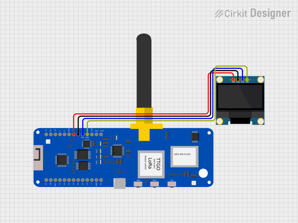

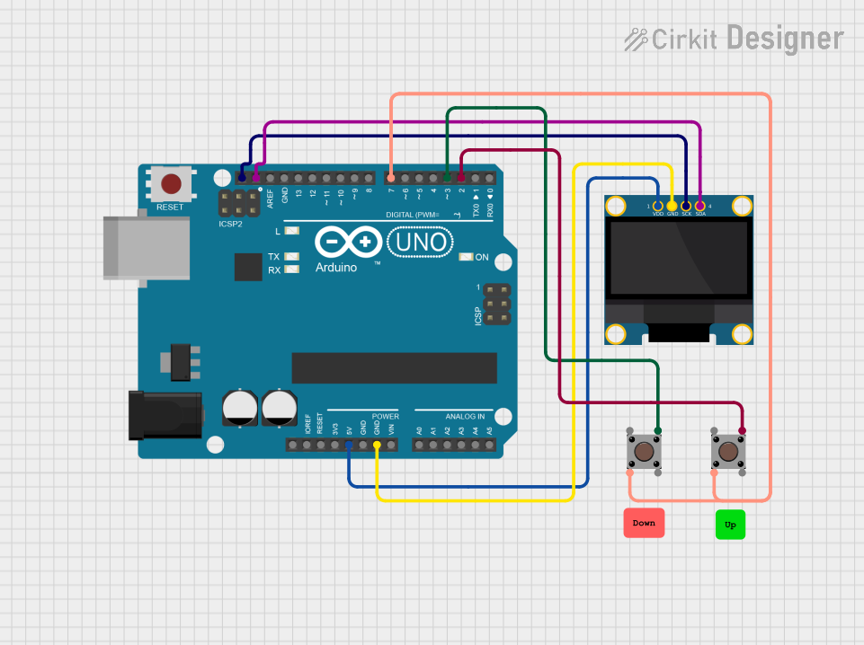

Explore Projects Built with OLED 128x64 I2C Monochrome Display VDD-GND
Technical Specifications
Key Technical Details
| Parameter | Value |
|---|---|
| Display Type | OLED Monochrome |
| Resolution | 128x64 pixels |
| Communication Protocol | I2C |
| Operating Voltage (VDD) | 3.3V to 5V |
| Current Consumption | ~20mA (typical) |
| Dimensions | ~27mm x 27mm x 4mm |
| Viewing Angle | >160° |
| Operating Temperature | -40°C to +85°C |
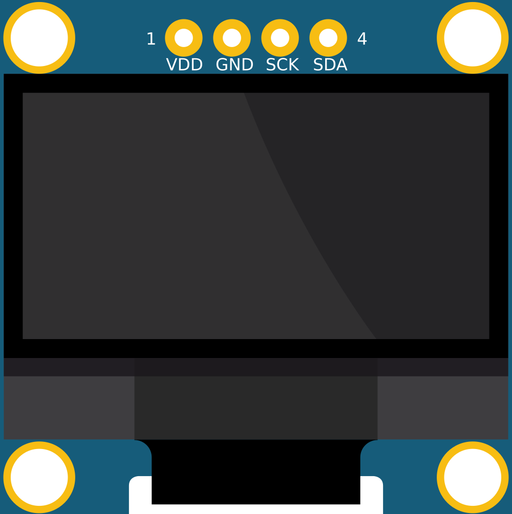
Pin Configuration and Descriptions
| Pin Name | Pin Number | Description |
|---|---|---|
| VDD | 1 | Power supply input (3.3V to 5V) |
| GND | 2 | Ground connection |
| SCL | 3 | I2C clock line (connect to microcontroller SCL) |
| SDA | 4 | I2C data line (connect to microcontroller SDA) |
Usage Instructions
How to Use the Component in a Circuit
- Power the Display: Connect the VDD pin to a 3.3V or 5V power source and the GND pin to the ground of your circuit.
- Connect I2C Lines:
- Connect the SCL pin to the I2C clock line of your microcontroller.
- Connect the SDA pin to the I2C data line of your microcontroller.
- Pull-Up Resistors: Ensure that the I2C lines (SCL and SDA) have pull-up resistors (typically 4.7kΩ to 10kΩ). Some modules include built-in pull-up resistors.
- Install Required Libraries: If using an Arduino, install the
Adafruit_GFXandAdafruit_SSD1306libraries via the Arduino Library Manager. - Write Code: Use the libraries to initialize the display and send data to it.
Example Code for Arduino UNO
#include <Wire.h>                 // Include the Wire library for I2C communication
#include <Adafruit_GFX.h>         // Include the Adafruit GFX library for graphics
#include <Adafruit_SSD1306.h>     // Include the Adafruit SSD1306 library for the OLED

#define SCREEN_WIDTH 128          // OLED display width, in pixels
#define SCREEN_HEIGHT 64          // OLED display height, in pixels

// Create an SSD1306 display object connected to I2C (default address 0x3C)
Adafruit_SSD1306 display(SCREEN_WIDTH, SCREEN_HEIGHT, &Wire, -1);

void setup() {
  // Initialize serial communication for debugging
  Serial.begin(9600);

  // Initialize the OLED display
  if (!display.begin(SSD1306_I2C_ADDRESS, 0x3C)) {
    Serial.println(F("SSD1306 allocation failed"));
    for (;;); // Loop forever if initialization fails
  }

  // Clear the display buffer
  display.clearDisplay();

  // Display a welcome message
  display.setTextSize(1);         // Set text size to 1 (smallest)
  display.setTextColor(SSD1306_WHITE); // Set text color to white
  display.setCursor(0, 0);        // Set cursor to top-left corner
  display.println(F("Hello, OLED!")); // Print text to the display
  display.display();              // Update the display with the text
  delay(2000);                    // Wait for 2 seconds
}

void loop() {
  // Example: Draw a rectangle and update the display
  display.clearDisplay();         // Clear the display buffer
  display.drawRect(10, 10, 50, 30, SSD1306_WHITE); // Draw a rectangle
  display.display();              // Update the display with the rectangle
  delay(1000);                    // Wait for 1 second
}
Important Considerations and Best Practices
- I2C Address: The default I2C address for most OLED modules is
0x3C. Verify this in the module's datasheet or documentation. - Power Supply: Ensure the power supply voltage matches the module's requirements (3.3V or 5V).
- Contrast and Brightness: Prolong the lifespan of the OLED by avoiding maximum brightness for extended periods.
- Library Compatibility: Use the latest versions of the
Adafruit_GFXandAdafruit_SSD1306libraries for optimal performance.
Troubleshooting and FAQs
Common Issues and Solutions
Display Not Turning On:
- Verify the power connections (VDD and GND).
- Check the I2C address and ensure it matches the one in your code.
- Ensure pull-up resistors are present on the I2C lines.
Flickering or Unstable Display:
- Check for loose connections on the I2C lines.
- Ensure the power supply is stable and within the specified voltage range.
Text or Graphics Not Displaying Properly:
- Verify that the correct resolution (128x64) is set in the code.
- Ensure the
Adafruit_SSD1306library is properly initialized.
I2C Communication Errors:
- Confirm that the SCL and SDA lines are connected to the correct pins on the microcontroller.
- Check for conflicting devices on the I2C bus.
FAQs
Q: Can I use this display with a 3.3V microcontroller?
A: Yes, the display is compatible with both 3.3V and 5V systems.
Q: How do I change the I2C address of the display?
A: Some modules allow changing the I2C address by soldering jumpers on the back of the PCB. Refer to the module's datasheet for details.
Q: Is it possible to display images on this OLED?
A: Yes, you can display monochrome bitmap images by converting them to the appropriate format using tools like the Adafruit ImageConverter.
Q: Can I use this display with a Raspberry Pi?
A: Absolutely! The display is compatible with Raspberry Pi and can be controlled using Python libraries like Adafruit-SSD1306.
By following this documentation, you can effectively integrate the OLED 128x64 I2C Monochrome Display into your projects.