How to Use ESP8266: Examples, Pinouts, and Specs
Introduction
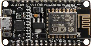
The ESP8266, manufactured by Lolin, is a low-cost Wi-Fi microchip with a full TCP/IP stack and microcontroller capability. It is widely used in Internet of Things (IoT) applications due to its affordability, compact size, and versatility. The ESP8266 can operate as both a standalone microcontroller or as a Wi-Fi module for other microcontrollers, making it a popular choice for hobbyists and professionals alike.
Explore Projects Built with ESP8266
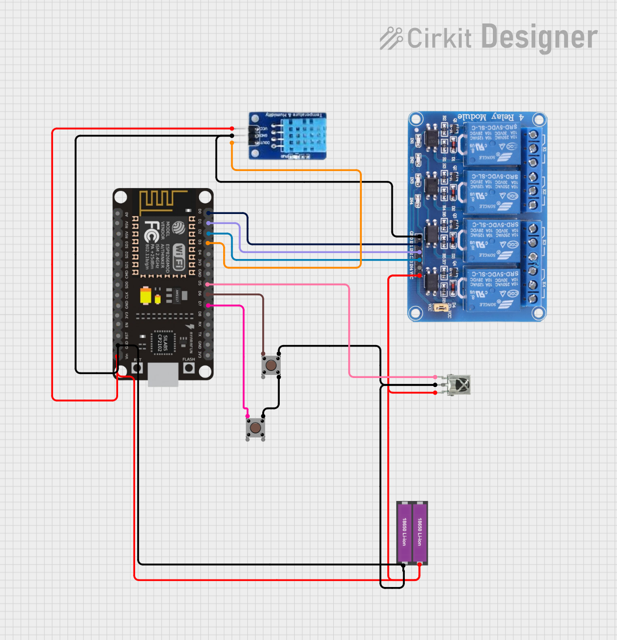

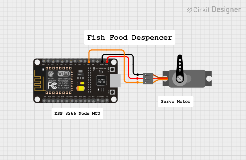

Explore Projects Built with ESP8266
Common Applications and Use Cases
- Home automation systems
- Smart appliances
- Wireless sensor networks
- IoT prototyping and development
- Remote monitoring and control systems
- Wi-Fi-enabled robotics
Technical Specifications
The ESP8266 is a highly integrated chip with the following key specifications:
| Parameter | Value |
|---|---|
| Manufacturer | Lolin |
| Part ID | ESP8266 |
| Operating Voltage | 3.0V - 3.6V |
| Flash Memory | 512 KB to 4 MB (varies by model) |
| RAM | 64 KB instruction RAM, 96 KB data RAM |
| Wi-Fi Standards | 802.11 b/g/n |
| Frequency Range | 2.4 GHz |
| GPIO Pins | Up to 17 (varies by module) |
| Communication Interfaces | UART, SPI, I2C, I2S, PWM, ADC |
| Maximum Current Draw | ~170 mA during Wi-Fi transmission |
| Operating Temperature | -40°C to 125°C |
| CPU | Tensilica L106 32-bit RISC processor, clocked at 80 MHz (up to 160 MHz) |
Pin Configuration and Descriptions
The ESP8266 is available in various module formats, such as the ESP-01, ESP-12E, and NodeMCU. Below is the pin configuration for the ESP-12E module, one of the most commonly used variants:
| Pin Name | Pin Number | Description |
|---|---|---|
| VCC | 1 | Power supply (3.3V). Do not exceed 3.6V. |
| GND | 2 | Ground connection. |
| TX | 3 | UART Transmit pin. Used for serial communication. |
| RX | 4 | UART Receive pin. Used for serial communication. |
| GPIO0 | 5 | General-purpose I/O pin. Used for boot mode selection during startup. |
| GPIO2 | 6 | General-purpose I/O pin. |
| GPIO15 | 7 | General-purpose I/O pin. Must be pulled LOW during boot. |
| EN (CH_PD) | 8 | Chip enable. Must be pulled HIGH to enable the chip. |
| RST | 9 | Reset pin. Pull LOW to reset the module. |
| ADC (A0) | 10 | Analog-to-digital converter input. Accepts voltages between 0V and 1V. |
Usage Instructions
The ESP8266 can be used as a standalone microcontroller or as a Wi-Fi module for other microcontrollers like the Arduino UNO. Below are the steps to use the ESP8266 in a circuit:
1. Powering the ESP8266
- The ESP8266 operates at 3.3V. Ensure that the power supply does not exceed this voltage, as higher voltages can damage the chip.
- Use a voltage regulator if your power source provides a higher voltage (e.g., 5V).
2. Connecting to an Arduino UNO
To use the ESP8266 with an Arduino UNO, follow these steps:
- Connect the TX pin of the ESP8266 to the RX pin of the Arduino (with a voltage divider if needed).
- Connect the RX pin of the ESP8266 to the TX pin of the Arduino.
- Connect the VCC and GND pins of the ESP8266 to a 3.3V power source and ground, respectively.
- Pull the EN pin HIGH and the GPIO15 pin LOW.
3. Programming the ESP8266
The ESP8266 can be programmed using the Arduino IDE. Below is an example code to connect the ESP8266 to a Wi-Fi network:
#include <ESP8266WiFi.h> // Include the ESP8266 Wi-Fi library

// Replace with your network credentials
const char* ssid = "Your_SSID";       // Your Wi-Fi network name
const char* password = "Your_Password"; // Your Wi-Fi network password

void setup() {
  Serial.begin(115200); // Initialize serial communication at 115200 baud
  delay(10);

  // Connect to Wi-Fi
  Serial.println("Connecting to Wi-Fi...");
  WiFi.begin(ssid, password);

  while (WiFi.status() != WL_CONNECTED) {
    delay(1000); // Wait for 1 second
    Serial.print("."); // Print a dot for each second of waiting
  }

  Serial.println("\nWi-Fi connected!");
  Serial.print("IP Address: ");
  Serial.println(WiFi.localIP()); // Print the assigned IP address
}

void loop() {
  // Add your main code here
}
4. Important Considerations
- Use a level shifter or voltage divider when connecting the ESP8266 to a 5V microcontroller to avoid damaging the module.
- Ensure proper decoupling capacitors are used near the power pins to stabilize the power supply.
- Avoid using the ESP8266 in environments with high electromagnetic interference (EMI).
Troubleshooting and FAQs
Common Issues and Solutions
ESP8266 not responding to AT commands:
- Ensure the baud rate in your serial monitor matches the default baud rate of the ESP8266 (usually 115200 or 9600).
- Check the wiring and ensure the module is powered correctly.
Wi-Fi connection fails:
- Double-check the SSID and password in your code.
- Ensure the Wi-Fi network is within range and not using unsupported security protocols.
Module overheating:
- Verify that the power supply is providing a stable 3.3V.
- Avoid prolonged high-current operations without proper heat dissipation.
ESP8266 resets frequently:
- Check for power supply issues. Use a capacitor (e.g., 10 µF) across the VCC and GND pins to stabilize the voltage.
- Ensure the EN pin is pulled HIGH and the GPIO15 pin is pulled LOW during boot.
FAQs
Q: Can the ESP8266 be programmed without an external microcontroller?
A: Yes, the ESP8266 has a built-in microcontroller and can be programmed directly using the Arduino IDE or other tools.
Q: What is the maximum range of the ESP8266 Wi-Fi module?
A: The range depends on the environment but is typically around 50 meters indoors and up to 100 meters outdoors.
Q: Can the ESP8266 handle HTTPS requests?
A: Yes, the ESP8266 supports HTTPS, but it may require additional libraries and sufficient flash memory.
Q: How do I update the firmware on the ESP8266?
A: Firmware updates can be performed using tools like the ESP8266 Flasher or the esptool.py utility.
By following this documentation, users can effectively integrate the ESP8266 into their projects and troubleshoot common issues.