How to Use 4s BMS: Examples, Pinouts, and Specs
Lisolec 4S Battery Management System (BMS) Documentation
1. Introduction
The Lisolec 4S Battery Management System (BMS) is a compact and efficient solution for managing lithium-ion battery packs consisting of four series-connected cells (4S configuration). This BMS is designed to ensure the safe operation of the battery pack by performing critical functions such as:
- Cell voltage balancing: Ensures all cells in the pack maintain equal voltage levels.
- Overcharge and over-discharge protection: Prevents damage to the cells by monitoring voltage thresholds.
- Temperature monitoring: Protects the battery pack from overheating during charging or discharging.
- Short-circuit and overcurrent protection: Safeguards the battery pack and connected devices.
Common Applications
The Lisolec 4S BMS is widely used in applications requiring reliable battery management, including:
- Electric bicycles and scooters
- Solar energy storage systems
- Uninterruptible Power Supplies (UPS)
- Portable power banks
- Robotics and IoT devices
2. Technical Specifications
The following table outlines the key technical details of the Lisolec 4S BMS:
| Parameter | Value |
|---|---|
| Battery Configuration | 4S (4 cells in series) |
| Input Voltage Range | 12.8V to 16.8V (nominal 14.8V) |
| Overcharge Protection | 4.25V ± 0.05V per cell |
| Over-discharge Protection | 2.7V ± 0.05V per cell |
| Balancing Voltage | 4.2V per cell |
| Balancing Current | 50mA |
| Maximum Continuous Current | 20A |
| Overcurrent Protection | 25A |
| Short-circuit Protection | Yes |
| Temperature Protection | Yes (Thermistor-based) |
| Dimensions | 60mm x 20mm x 3mm |
| Weight | 15g |
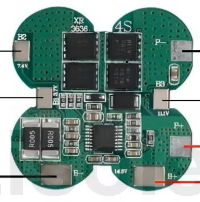
Pin Configuration and Descriptions
The Lisolec 4S BMS has the following pin configuration:
| Pin Name | Description |
|---|---|
| B- | Battery pack negative terminal |
| B1 | Connection to the positive terminal of the first cell |
| B2 | Connection to the positive terminal of the second cell |
| B3 | Connection to the positive terminal of the third cell |
| B4 | Connection to the positive terminal of the fourth cell |
| P- | Power output negative terminal (connect to load or charger negative terminal) |
| P+ | Power output positive terminal (connect to load or charger positive terminal) |
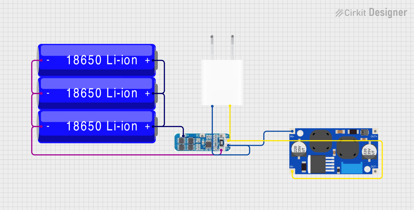
3. Usage Instructions
Connecting the Lisolec 4S BMS to a Battery Pack
- Prepare the Battery Pack: Ensure the battery pack consists of four series-connected lithium-ion cells. Verify that the cells are of the same type, capacity, and charge level.
- Connect the BMS:
- Connect the B- pin to the negative terminal of the battery pack.
- Connect the B1, B2, B3, and B4 pins to the positive terminals of the first, second, third, and fourth cells, respectively.
- Connect the P- and P+ pins to the load or charger as required.
- Verify Connections: Double-check all connections to ensure proper polarity and secure connections.
Important Considerations
- Cell Matching: Use cells with identical capacities and charge levels to ensure proper balancing and operation.
- Heat Dissipation: Ensure adequate ventilation or heat sinking to prevent overheating during high-current operation.
- Avoid Overloading: Do not exceed the maximum continuous current rating of 20A.
- Temperature Monitoring: Place the thermistor in close proximity to the battery pack for accurate temperature readings.
4. Example Arduino Integration
The Lisolec 4S BMS can be monitored using an Arduino UNO to read cell voltages and temperature. Below is an example code to interface the BMS with an Arduino using an analog-to-digital converter (ADC) for voltage monitoring and a thermistor for temperature sensing.
Wiring Diagram
- Connect the B1, B2, B3, and B4 pins to the analog input pins of the Arduino (e.g., A0, A1, A2, A3).
- Connect the thermistor output to another analog input pin (e.g., A4).
Arduino Code
// Lisolec 4S BMS Monitoring with Arduino UNO
// Reads cell voltages and temperature using analog inputs

// Define analog input pins for cell voltages
const int cell1Pin = A0; // B1 pin
const int cell2Pin = A1; // B2 pin
const int cell3Pin = A2; // B3 pin
const int cell4Pin = A3; // B4 pin

// Define analog input pin for thermistor
const int tempPin = A4;

// Voltage divider ratio (if used)
const float voltageDividerRatio = 2.0; // Adjust based on your circuit

// Function to read cell voltage
float readCellVoltage(int pin) {
  int rawValue = analogRead(pin); // Read ADC value (0-1023)
  float voltage = (rawValue * 5.0) / 1023.0; // Convert to voltage
  return voltage * voltageDividerRatio; // Adjust for divider
}

// Function to read temperature (example for 10k thermistor)
float readTemperature(int pin) {
  int rawValue = analogRead(pin);
  float resistance = (1023.0 / rawValue - 1.0) * 10000.0; // Calculate resistance
  float temperature = 1.0 / (0.001129148 + (0.000234125 * log(resistance)) +
                             (0.0000000876741 * pow(log(resistance), 3)));
  return temperature - 273.15; // Convert to Celsius
}

void setup() {
  Serial.begin(9600); // Initialize serial communication
}

void loop() {
  // Read and print cell voltages
  float cell1Voltage = readCellVoltage(cell1Pin);
  float cell2Voltage = readCellVoltage(cell2Pin);
  float cell3Voltage = readCellVoltage(cell3Pin);
  float cell4Voltage = readCellVoltage(cell4Pin);

  Serial.print("Cell 1 Voltage: "); Serial.println(cell1Voltage);
  Serial.print("Cell 2 Voltage: "); Serial.println(cell2Voltage);
  Serial.print("Cell 3 Voltage: "); Serial.println(cell3Voltage);
  Serial.print("Cell 4 Voltage: "); Serial.println(cell4Voltage);

  // Read and print temperature
  float temperature = readTemperature(tempPin);
  Serial.print("Temperature: "); Serial.print(temperature); Serial.println(" °C");

  delay(1000); // Wait 1 second before next reading
}
5. Troubleshooting and FAQs
Common Issues and Solutions
| Issue | Possible Cause | Solution |
|---|---|---|
| BMS not powering on | Incorrect wiring or loose connections | Verify all connections and ensure proper polarity. |
| Cells not balancing | Voltage difference between cells is too high | Pre-charge all cells to similar voltage levels before connecting to the BMS. |
| Overheating during operation | Exceeding current rating or poor ventilation | Reduce load current or improve heat dissipation. |
| No output voltage | Over-discharge protection activated | Recharge the battery pack to restore normal operation. |
FAQs
Can I use the Lisolec 4S BMS with fewer than 4 cells?
- No, this BMS is specifically designed for 4S configurations. Using fewer cells may result in improper operation.
What happens if one cell fails?
- The BMS will detect the imbalance and may shut down to protect the pack. Replace the faulty cell immediately.
Can I use this BMS for LiFePO4 cells?
- Yes, but ensure the voltage thresholds are compatible with LiFePO4 chemistry.
This concludes the documentation for the Lisolec 4S Battery Management System (BMS). For further assistance, contact Lisolec support or refer to the product datasheet.
Explore Projects Built with 4s BMS


Explore Projects Built with 4s BMS