How to Use display: Examples, Pinouts, and Specs
Introduction
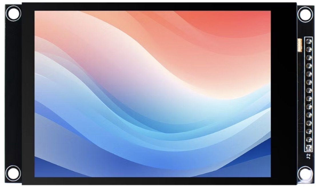
A display is an output device that visually presents information, such as text, images, or video, allowing users to interact with electronic devices. Displays are integral to modern electronics, ranging from simple alphanumeric LCDs to advanced OLED and TFT screens capable of rendering high-resolution graphics. They are widely used in consumer electronics, industrial equipment, and embedded systems.
Explore Projects Built with display

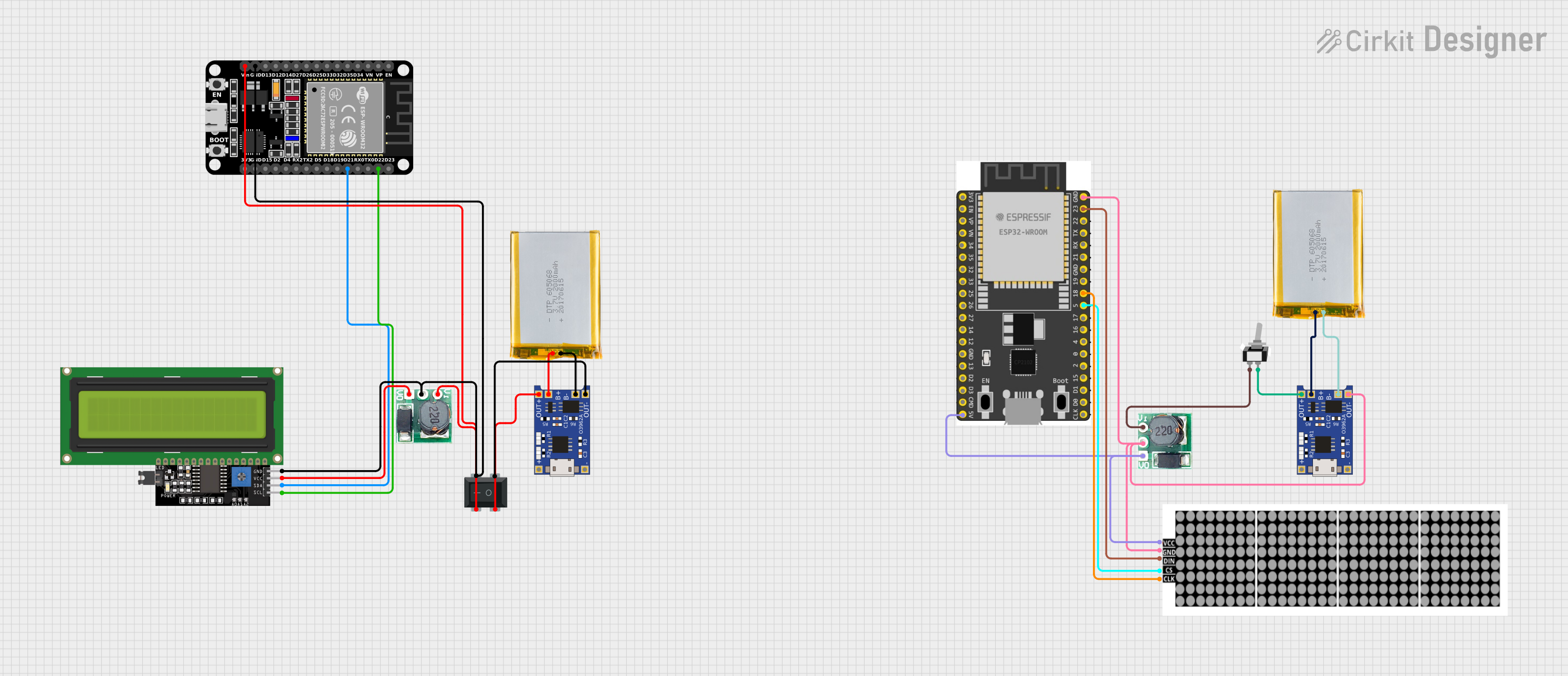
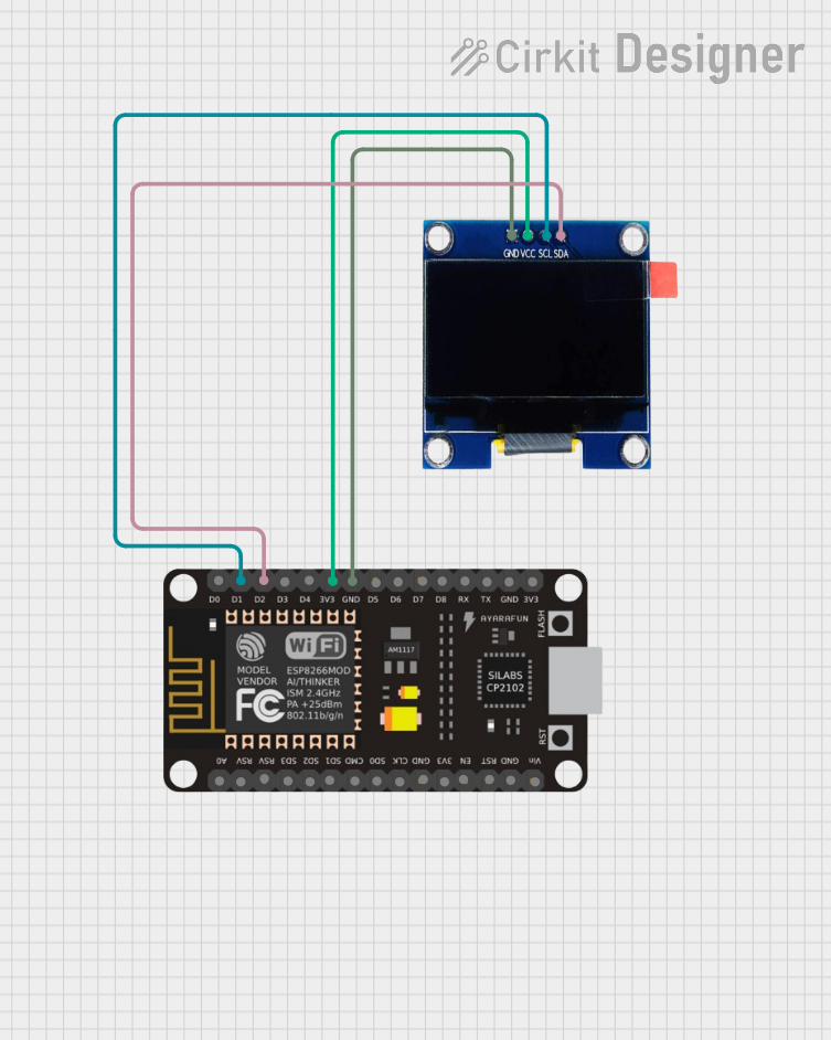
Explore Projects Built with display
Common Applications and Use Cases
- Consumer Electronics: Smartphones, tablets, and televisions.
- Embedded Systems: Microcontroller-based projects, such as Arduino or Raspberry Pi.
- Industrial Equipment: Control panels and monitoring systems.
- Wearable Devices: Smartwatches and fitness trackers.
- Prototyping: Visual feedback for DIY electronics projects.
Technical Specifications
The specifications of a display vary depending on the type and model. Below is an example of a common 16x2 alphanumeric LCD display (HD44780-compatible):
General Specifications
- Display Type: Alphanumeric LCD
- Resolution: 16 characters x 2 lines
- Operating Voltage: 4.7V to 5.3V
- Current Consumption: ~1mA (without backlight), ~15mA (with backlight)
- Interface: Parallel (4-bit or 8-bit mode)
- Backlight: LED (optional, controllable)
Pin Configuration and Descriptions
The 16x2 LCD typically has 16 pins. Below is the pinout:
| Pin Number | Name | Description |
|---|---|---|
| 1 | VSS | Ground (0V) |
| 2 | VDD | Power supply (4.7V to 5.3V) |
| 3 | VO | Contrast adjustment (connect to a potentiometer) |
| 4 | RS | Register Select (0: Command mode, 1: Data mode) |
| 5 | RW | Read/Write (0: Write, 1: Read) |
| 6 | E | Enable signal (triggers data read/write) |
| 7 | D0 | Data bit 0 (used in 8-bit mode only) |
| 8 | D1 | Data bit 1 (used in 8-bit mode only) |
| 9 | D2 | Data bit 2 (used in 8-bit mode only) |
| 10 | D3 | Data bit 3 (used in 8-bit mode only) |
| 11 | D4 | Data bit 4 (used in 4-bit or 8-bit mode) |
| 12 | D5 | Data bit 5 (used in 4-bit or 8-bit mode) |
| 13 | D6 | Data bit 6 (used in 4-bit or 8-bit mode) |
| 14 | D7 | Data bit 7 (used in 4-bit or 8-bit mode) |
| 15 | A | LED backlight anode (connect to +5V via a resistor) |
| 16 | K | LED backlight cathode (connect to ground) |
Usage Instructions
How to Use the Component in a Circuit
- Power the Display: Connect the VSS pin to ground and the VDD pin to a 5V power source.
- Adjust Contrast: Connect the VO pin to the wiper of a 10kΩ potentiometer. Connect one end of the potentiometer to ground and the other to 5V.
- Connect Control Pins:
- RS, RW, and E pins should be connected to digital pins of a microcontroller.
- For write-only operation, connect RW to ground.
- Connect Data Pins:
- In 4-bit mode, use only D4 to D7. Leave D0 to D3 unconnected.
- In 8-bit mode, connect all data pins (D0 to D7) to the microcontroller.
- Backlight: Connect the A pin to 5V through a 220Ω resistor and the K pin to ground.
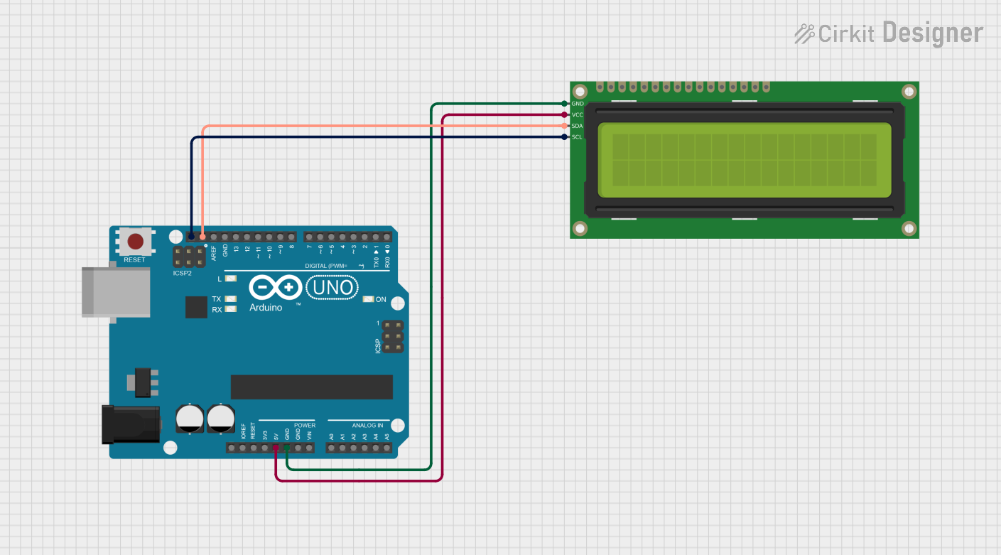
Example: Connecting to an Arduino UNO
Below is an example of how to connect and program a 16x2 LCD with an Arduino UNO in 4-bit mode.
Circuit Connections
- RS: Connect to Arduino digital pin 7.
- E: Connect to Arduino digital pin 8.
- D4 to D7: Connect to Arduino digital pins 9, 10, 11, and 12, respectively.
- RW: Connect to ground.
- VO: Connect to the wiper of a 10kΩ potentiometer for contrast adjustment.
- A and K: Connect to 5V and ground, respectively, with a 220Ω resistor in series with A.
Arduino Code
#include <LiquidCrystal.h>

// Initialize the library with the numbers of the interface pins
LiquidCrystal lcd(7, 8, 9, 10, 11, 12);

void setup() {
  // Set up the LCD's number of columns and rows
  lcd.begin(16, 2);

  // Print a message to the LCD
  lcd.print("Hello, World!");
}

void loop() {
  // Set the cursor to column 0, line 1
  lcd.setCursor(0, 1);

  // Print the current time in seconds since the Arduino started
  lcd.print(millis() / 1000);
}
Important Considerations and Best Practices
- Contrast Adjustment: Ensure the potentiometer is properly adjusted for optimal text visibility.
- Backlight Current: Use a resistor to limit the current through the backlight LED to prevent damage.
- Noise Reduction: Keep data and control lines as short as possible to reduce noise.
- Power Supply: Ensure a stable 5V power supply to avoid flickering or erratic behavior.
Troubleshooting and FAQs
Common Issues and Solutions
No Display Output:
- Check power connections (VSS and VDD).
- Verify contrast adjustment (VO pin).
- Ensure the RS, E, and data pins are correctly connected.
Flickering or Unstable Display:
- Use decoupling capacitors (e.g., 0.1µF) near the power pins.
- Check for loose or noisy connections.
Incorrect Characters Displayed:
- Verify the data pin connections.
- Ensure the correct mode (4-bit or 8-bit) is configured in the code.
Backlight Not Working:
- Check the resistor value in series with the A pin.
- Verify the backlight pins (A and K) are properly connected.
FAQs
Can I use the display with 3.3V logic?
- Most 16x2 LCDs require 5V for operation. Use a level shifter if interfacing with a 3.3V microcontroller.
How do I display custom characters?
- Use the
createChar()function in the LiquidCrystal library to define custom characters.
- Use the
Can I use the display without a backlight?
- Yes, the display will still function, but visibility may be reduced in low-light conditions.