
How to Use iPod Female Connector: Examples, Pinouts, and Specs
 Design with iPod Female Connector in Cirkit Designer
Introduction
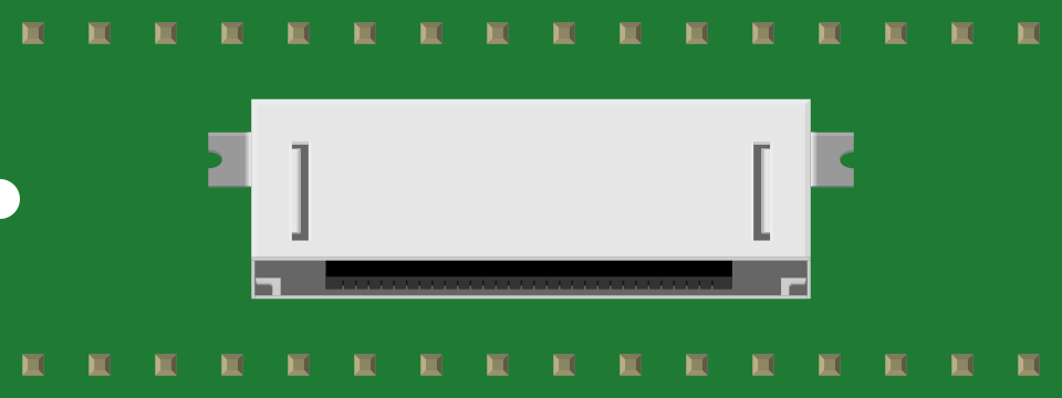
The iPod Female Connector is a specialized interface designed to connect with iPod devices. It facilitates both data transfer and charging, making it an essential component for creating custom docks, chargers, or audio systems compatible with iPods. This connector is widely used in consumer electronics, DIY projects, and repair applications.
Explore Projects Built with iPod Female Connector
 Open Project in Cirkit Designer
 Open Project in Cirkit Designer
 Open Project in Cirkit Designer
 Open Project in Cirkit Designer
Explore Projects Built with iPod Female Connector
Open Project in Cirkit DesignerOpen Project in Cirkit DesignerOpen Project in Cirkit DesignerOpen Project in Cirkit DesignerCommon Applications and Use Cases
- Custom iPod docking stations
- Audio systems with iPod compatibility
- DIY charging and data transfer cables
- Repair and replacement of damaged iPod connectors
- Integration into embedded systems for iPod communication
Technical Specifications
Key Technical Details
- Connector Type: 30-pin female connector
- Voltage Rating: 5V DC (for charging)
- Current Rating: Up to 2.1A (depending on the iPod model)
- Data Protocol: USB 2.0 or Apple-specific serial communication
- Compatibility: Supports most iPod models with a 30-pin interface
- Dimensions: Standard 30-pin connector size (approx. 21mm width)
Pin Configuration and Descriptions
The iPod Female Connector has 30 pins, each serving a specific function. Below is a table summarizing the key pin assignments:
| Pin Number | Function | Description |
|---|---|---|
| 1 | GND | Ground connection |
| 2 | +5V Power | Power supply for charging (5V DC) |
| 3 | USB D+ | USB data positive line |
| 4 | USB D- | USB data negative line |
| 5 | Accessory Detect | Detects connected accessories |
| 6 | Audio L | Left audio channel output |
| 7 | Audio R | Right audio channel output |
| 8 | Audio GND | Ground for audio signals |
| 9 | Serial TX | Transmit line for Apple-specific serial communication |
| 10 | Serial RX | Receive line for Apple-specific serial communication |
| 11-30 | Reserved/Proprietary | Reserved for Apple-specific functions (e.g., video out, accessory control) |
Note: Not all pins are required for basic charging or data transfer. Refer to your specific application to determine which pins are necessary.
Usage Instructions
How to Use the Component in a Circuit
- Identify Required Pins: Determine which pins are needed for your application (e.g., charging, data transfer, or audio output).
- Soldering: Carefully solder wires to the appropriate pins on the connector. Use a fine-tipped soldering iron and ensure no pins are shorted.
- Power Supply: Provide a stable 5V DC power source to the +5V Power pin (Pin 2) and connect the GND pin (Pin 1) to the ground of your circuit.
- Data Communication: For USB data transfer, connect the USB D+ (Pin 3) and USB D- (Pin 4) lines to a USB interface.
- Audio Output: To extract audio, connect the Audio L (Pin 6), Audio R (Pin 7), and Audio GND (Pin 8) pins to an amplifier or speaker system.
- Accessory Detection: Use the Accessory Detect pin (Pin 5) to identify when an iPod is connected.
Important Considerations and Best Practices
- Avoid Overheating: Excessive heat during soldering can damage the connector. Use a low-temperature soldering iron and work quickly.
- Pin Protection: Ensure unused pins are insulated to prevent accidental shorts.
- Power Regulation: Use a regulated 5V power supply to avoid damaging the iPod.
- Compatibility Check: Verify that your iPod model supports the 30-pin connector before use.
- Cable Strain Relief: If using the connector in a cable assembly, add strain relief to prevent damage to solder joints.
Example: Connecting to an Arduino UNO
The iPod Female Connector can be used with an Arduino UNO for basic serial communication. Below is an example code snippet to establish communication:
// Example: Serial communication with iPod using Arduino UNO
// Connect Serial TX (Pin 9) of the iPod connector to Arduino RX (Pin 0)
// Connect Serial RX (Pin 10) of the iPod connector to Arduino TX (Pin 1)
// Ensure GND (Pin 1) is connected to Arduino GND

void setup() {
  Serial.begin(9600); // Initialize serial communication at 9600 baud
  Serial.println("Arduino ready to communicate with iPod");
}

void loop() {
  if (Serial.available()) {
    char data = Serial.read(); // Read data from iPod
    Serial.print("Received: ");
    Serial.println(data); // Print received data to Serial Monitor
  }
}
Note: Ensure the iPod is in a mode that allows serial communication. Some models may require specific initialization commands.
Troubleshooting and FAQs
Common Issues Users Might Face
No Charging:
- Cause: Incorrect power supply or loose connections.
- Solution: Verify the 5V power supply and ensure proper soldering of the +5V and GND pins.
No Data Transfer:
- Cause: Miswired USB D+ and D- lines or incompatible iPod model.
- Solution: Double-check the wiring and ensure the iPod supports USB data transfer.
Audio Output Not Working:
- Cause: Incorrect wiring of audio pins or missing ground connection.
- Solution: Verify connections to Audio L, Audio R, and Audio GND pins.
Overheating During Soldering:
- Cause: Prolonged exposure to heat.
- Solution: Use a low-temperature soldering iron and minimize contact time.
Solutions and Tips for Troubleshooting
- Use a multimeter to check continuity and verify connections.
- Refer to the iPod's technical documentation for specific pinout details.
- Test the connector with a known working iPod to rule out device-related issues.
- If using the connector for serial communication, ensure the baud rate matches between devices.
By following this documentation, you can effectively integrate the iPod Female Connector into your projects and troubleshoot common issues with ease.