Cirkit Designer
Your all-in-one circuit design IDE
Home /
Component Documentation
How to Use 128pinout: Examples, Pinouts, and Specs
Introduction
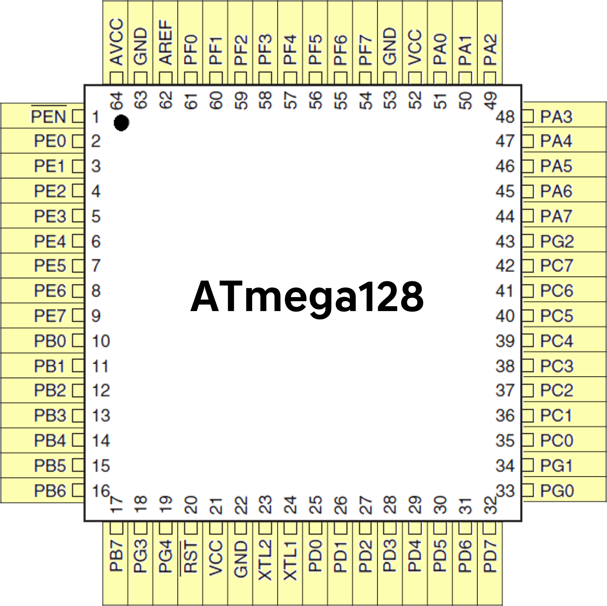
The ATmega128 is a high-performance, low-power 8-bit microcontroller from Custom. It features a 128-pinout, which provides extensive connectivity options for various applications. This microcontroller is widely used in embedded systems, robotics, and industrial automation due to its robust performance and versatility.
Explore Projects Built with 128pinout
5-Pin Connector Synchronization Circuit

This circuit consists of four 5-pin connectors, where two of the connectors are fully interconnected pin-to-pin. The purpose of this setup could be to create a parallel connection between the two 5-pin connectors, possibly for signal distribution or redundancy.
4-Pin Connector Circuit for Edge Detection

This circuit appears to be a simple interconnection of pins and points, with a 4-pin component serving as a central hub. The red and black pins of the 4-pin component are connected to various other pins and edge components, forming a basic network of connections without any active components or microcontroller logic.
ESP32-Based OLED Display Interface

This circuit features an ESP32 microcontroller connected to an OLED 1.3" display. The ESP32's GPIO pins 21 and 22 are used for I2C communication (SDA and SCL respectively) with the OLED display. The display is powered by the 5V output from the ESP32, and both devices share a common ground.
ESP8266 NodeMCU Controlled 8x8 LED Matrix Display
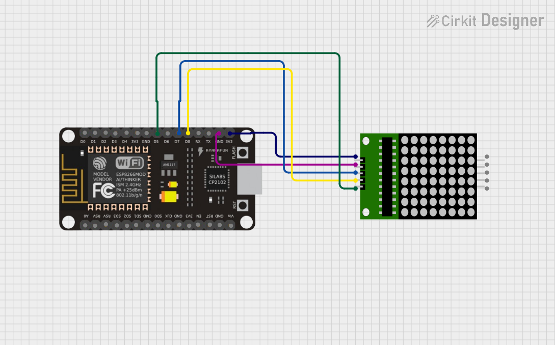
This circuit connects an ESP8266 NodeMCU microcontroller to an 8x8 LED matrix display. The NodeMCU controls the matrix using digital pins D5, D7, and D8 for chip select (CS), data input (DIN), and clock (CLK) signals, respectively. The circuit is designed to display patterns or characters on the LED matrix, which are driven by the microcontroller.
Explore Projects Built with 128pinout
5-Pin Connector Synchronization Circuit
This circuit consists of four 5-pin connectors, where two of the connectors are fully interconnected pin-to-pin. The purpose of this setup could be to create a parallel connection between the two 5-pin connectors, possibly for signal distribution or redundancy.
4-Pin Connector Circuit for Edge Detection
This circuit appears to be a simple interconnection of pins and points, with a 4-pin component serving as a central hub. The red and black pins of the 4-pin component are connected to various other pins and edge components, forming a basic network of connections without any active components or microcontroller logic.
ESP32-Based OLED Display Interface
This circuit features an ESP32 microcontroller connected to an OLED 1.3" display. The ESP32's GPIO pins 21 and 22 are used for I2C communication (SDA and SCL respectively) with the OLED display. The display is powered by the 5V output from the ESP32, and both devices share a common ground.
ESP8266 NodeMCU Controlled 8x8 LED Matrix Display
This circuit connects an ESP8266 NodeMCU microcontroller to an 8x8 LED matrix display. The NodeMCU controls the matrix using digital pins D5, D7, and D8 for chip select (CS), data input (DIN), and clock (CLK) signals, respectively. The circuit is designed to display patterns or characters on the LED matrix, which are driven by the microcontroller.
Common Applications and Use Cases
- Embedded Systems: Ideal for complex embedded applications requiring multiple I/O ports.
- Robotics: Used in robotic controllers for precise control and communication.
- Industrial Automation: Suitable for automation systems needing reliable and efficient processing.
- Consumer Electronics: Employed in various consumer devices for enhanced functionality.
Technical Specifications
Key Technical Details
| Parameter | Value |
|---|---|
| Operating Voltage | 2.7V - 5.5V |
| Maximum Frequency | 16 MHz |
| Flash Memory | 128 KB |
| SRAM | 4 KB |
| EEPROM | 4 KB |
| I/O Pins | 86 |
| ADC Channels | 8 |
| Timers | 4 (8-bit and 16-bit) |
| Communication | UART, SPI, I2C |
| Power Consumption | Low Power Consumption Modes |
Pin Configuration and Descriptions
| Pin Number | Pin Name | Description |
|---|---|---|
| 1 | VCC | Power Supply |
| 2 | GND | Ground |
| 3 | PA0 | ADC Channel 0 / Digital I/O |
| 4 | PA1 | ADC Channel 1 / Digital I/O |
| ... | ... | ... |
| 128 | PC7 | Digital I/O |
Note: For a complete pin configuration, refer to the ATmega128 datasheet.
Usage Instructions
How to Use the Component in a Circuit
Power Supply:
- Connect the VCC pin to a stable power supply (2.7V - 5.5V).
- Connect the GND pin to the ground of the circuit.
I/O Configuration:
- Configure the I/O pins as input or output based on your application.
- Use internal pull-up resistors if necessary.
Communication:
- Utilize UART, SPI, or I2C for communication with other devices.
- Ensure proper configuration of communication protocols.
Programming:
- Use an appropriate programmer to upload code to the ATmega128.
- Ensure the correct fuse settings for desired operation.
Important Considerations and Best Practices
- Decoupling Capacitors: Place decoupling capacitors close to the power pins to filter noise.
- Clock Source: Use a stable clock source for accurate timing.
- Reset Pin: Connect a pull-up resistor to the reset pin to avoid unintended resets.
- Heat Dissipation: Ensure proper heat dissipation to avoid overheating.
Example: Connecting to an Arduino UNO
// Example code to interface ATmega128 with Arduino UNO
// This code blinks an LED connected to PA0

void setup() {
  pinMode(22, OUTPUT); // PA0 is connected to pin 22 on Arduino
}

void loop() {
  digitalWrite(22, HIGH); // Turn the LED on
  delay(1000);            // Wait for a second
  digitalWrite(22, LOW);  // Turn the LED off
  delay(1000);            // Wait for a second
}
Troubleshooting and FAQs
Common Issues Users Might Face
Microcontroller Not Responding:
- Solution: Check the power supply and ensure proper connections.
Incorrect I/O Behavior:
- Solution: Verify the pin configuration and ensure correct programming.
Communication Failure:
- Solution: Check the communication protocol settings and connections.
Overheating:
- Solution: Ensure proper heat dissipation and check for excessive current draw.
Solutions and Tips for Troubleshooting
- Check Connections: Ensure all connections are secure and correct.
- Use a Multimeter: Measure voltages and continuity to diagnose issues.
- Refer to Datasheet: Consult the ATmega128 datasheet for detailed information.
- Update Firmware: Ensure the microcontroller firmware is up to date.
By following this documentation, users can effectively utilize the ATmega128 microcontroller in their projects, ensuring reliable and efficient performance.