How to Use Interruptor Diferencial: Examples, Pinouts, and Specs
Introduction
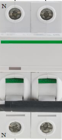
The Interruptor Diferencial, also known as a Residual Current Device (RCD), is an essential safety component in electrical systems. It is designed to protect users from electric shocks and prevent electrical fires by disconnecting the power supply when it detects an imbalance between the live and neutral currents. This imbalance typically indicates a leakage current, which could be caused by faulty wiring or contact with a live conductor.
Explore Projects Built with Interruptor Diferencial
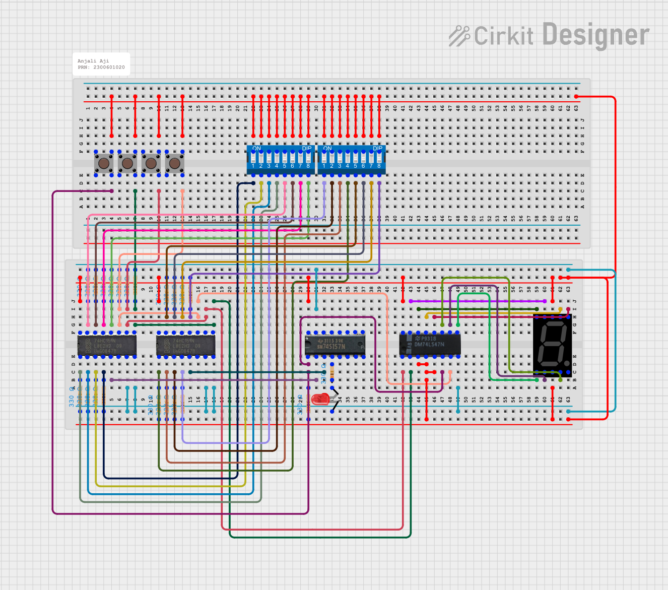
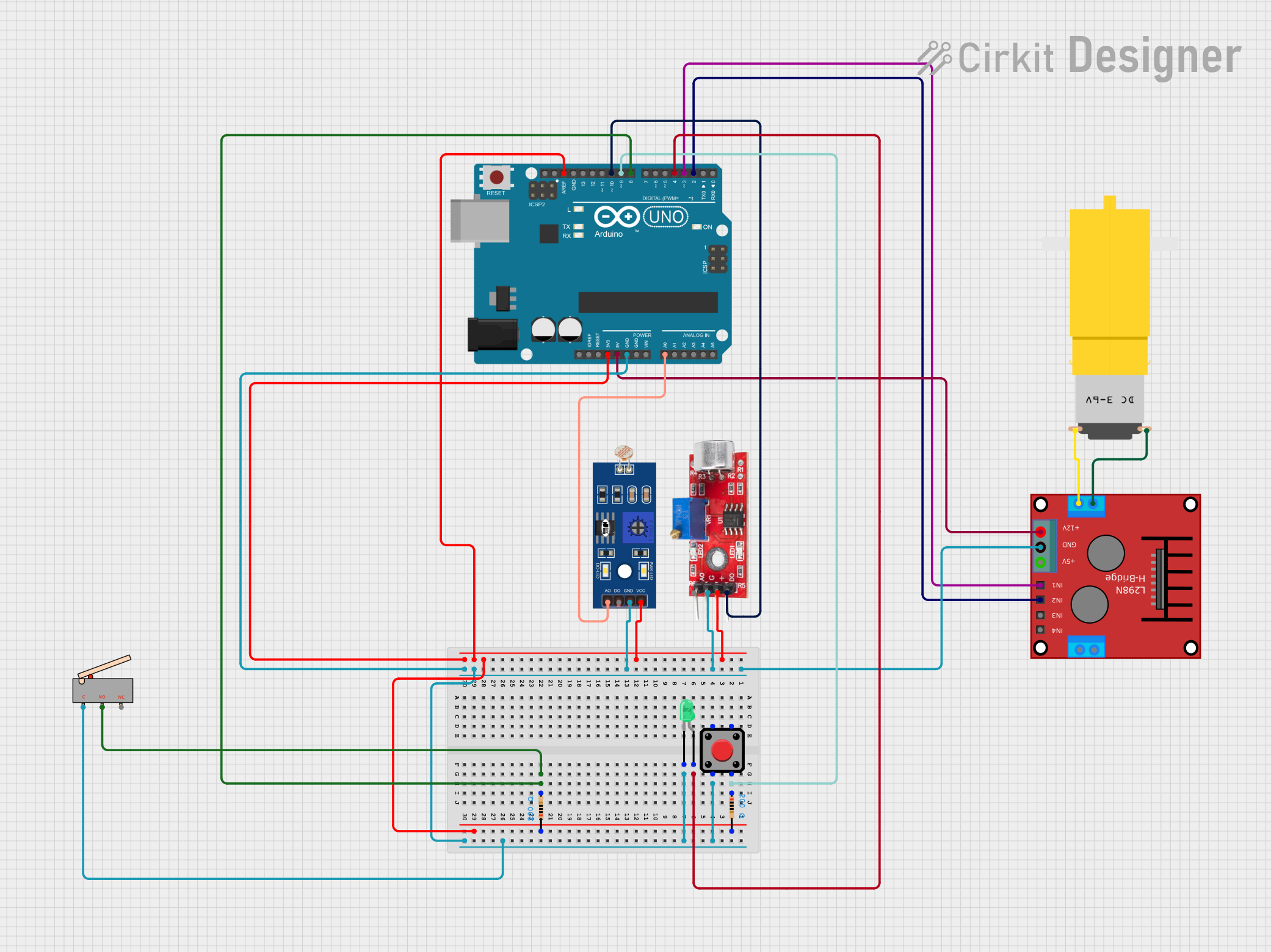

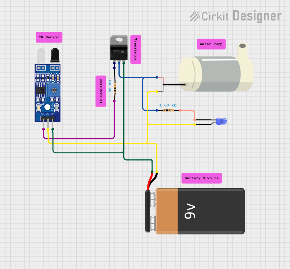
Explore Projects Built with Interruptor Diferencial
Common Applications and Use Cases
- Residential and commercial electrical installations for human safety.
- Industrial environments to protect equipment and personnel.
- Outdoor electrical systems, such as garden lighting or pool equipment.
- Temporary power setups, such as construction sites or event installations.
Technical Specifications
Key Technical Details
| Parameter | Value/Range |
|---|---|
| Rated Voltage | 230V AC (single-phase) or 400V AC (three-phase) |
| Rated Current | 16A, 25A, 40A, 63A (varies by model) |
| Rated Residual Current (IΔn) | 10mA, 30mA, 100mA, 300mA |
| Frequency | 50/60 Hz |
| Breaking Capacity | 6kA or higher |
| Operating Temperature Range | -25°C to +40°C |
| Mounting Type | DIN rail |
| Standards Compliance | IEC 61008, IEC 61009 |
Pin Configuration and Descriptions
The Interruptor Diferencial typically has four terminals for single-phase systems or eight terminals for three-phase systems. Below is the pin configuration for a single-phase RCD:
| Terminal Number | Label | Description |
|---|---|---|
| 1 | L (In) | Live input from the power source |
| 2 | N (In) | Neutral input from the power source |
| 3 | L (Out) | Live output to the load |
| 4 | N (Out) | Neutral output to the load |
For three-phase systems, additional terminals are provided for the three live phases (L1, L2, L3) and their corresponding outputs.
Usage Instructions
How to Use the Component in a Circuit
Wiring the RCD:
- Connect the live (L) and neutral (N) wires from the power source to the input terminals (1 and 2).
- Connect the live (L) and neutral (N) wires leading to the load to the output terminals (3 and 4).
- For three-phase systems, ensure all three live phases (L1, L2, L3) and neutral are correctly connected.
Testing the RCD:
- Most RCDs have a built-in test button. Press this button periodically to ensure the device is functioning correctly. The RCD should trip immediately when the test button is pressed.
Installation Best Practices:
- Always install the RCD on a DIN rail in a distribution board.
- Ensure the rated current and residual current match the requirements of your electrical system.
- Use appropriate wire gauges to handle the rated current safely.
Integration with Microcontrollers:
- While RCDs are not typically interfaced directly with microcontrollers like Arduino, you can monitor their status using auxiliary contacts (if available) or external sensors to detect tripping events.
Important Considerations and Best Practices
- Select the Correct Rating: Choose an RCD with a residual current rating suitable for the application (e.g., 30mA for personal protection, 300mA for fire prevention).
- Regular Testing: Test the RCD monthly using the test button to ensure it remains operational.
- Avoid Overloading: Do not exceed the rated current of the RCD, as this may cause overheating or failure.
- Proper Grounding: Ensure the electrical system is properly grounded to enhance the effectiveness of the RCD.
Troubleshooting and FAQs
Common Issues and Solutions
| Issue | Possible Cause | Solution |
|---|---|---|
| RCD does not trip when test button is pressed | Faulty RCD or incorrect wiring | Verify wiring and replace the RCD if necessary. |
| RCD trips frequently | Leakage current in the circuit | Inspect the wiring and connected devices for faults. |
| RCD does not reset after tripping | Persistent fault in the circuit | Disconnect all loads and test the circuit for faults. |
| RCD trips randomly | Nuisance tripping due to transient currents | Use an RCD with a higher residual current rating (e.g., 100mA). |
FAQs
Can I use an RCD without grounding?
- No, proper grounding is essential for the RCD to function effectively and ensure safety.
What is the difference between an RCD and an MCB?
- An RCD protects against leakage currents (electric shocks), while an MCB (Miniature Circuit Breaker) protects against overcurrent and short circuits.
How often should I test my RCD?
- It is recommended to test the RCD monthly using the test button.
Can an RCD protect against lightning strikes?
- No, an RCD is not designed to protect against lightning strikes. Use a surge protection device for this purpose.
By following this documentation, you can safely and effectively use an Interruptor Diferencial in your electrical systems.