How to Use 7-20V to 5V: Examples, Pinouts, and Specs
Introduction
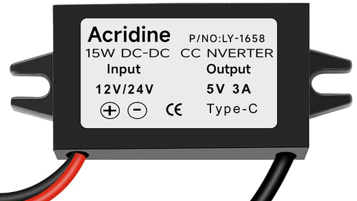
The 7-20V to 5V voltage regulator is a compact and efficient electronic component designed to step down an input voltage ranging from 7 to 20 volts to a stable 5-volt output. This regulator is widely used in powering low-voltage devices such as microcontrollers, sensors, and communication modules. Its ability to provide a consistent 5V output makes it an essential component in embedded systems, robotics, and DIY electronics projects.
Explore Projects Built with 7-20V to 5V


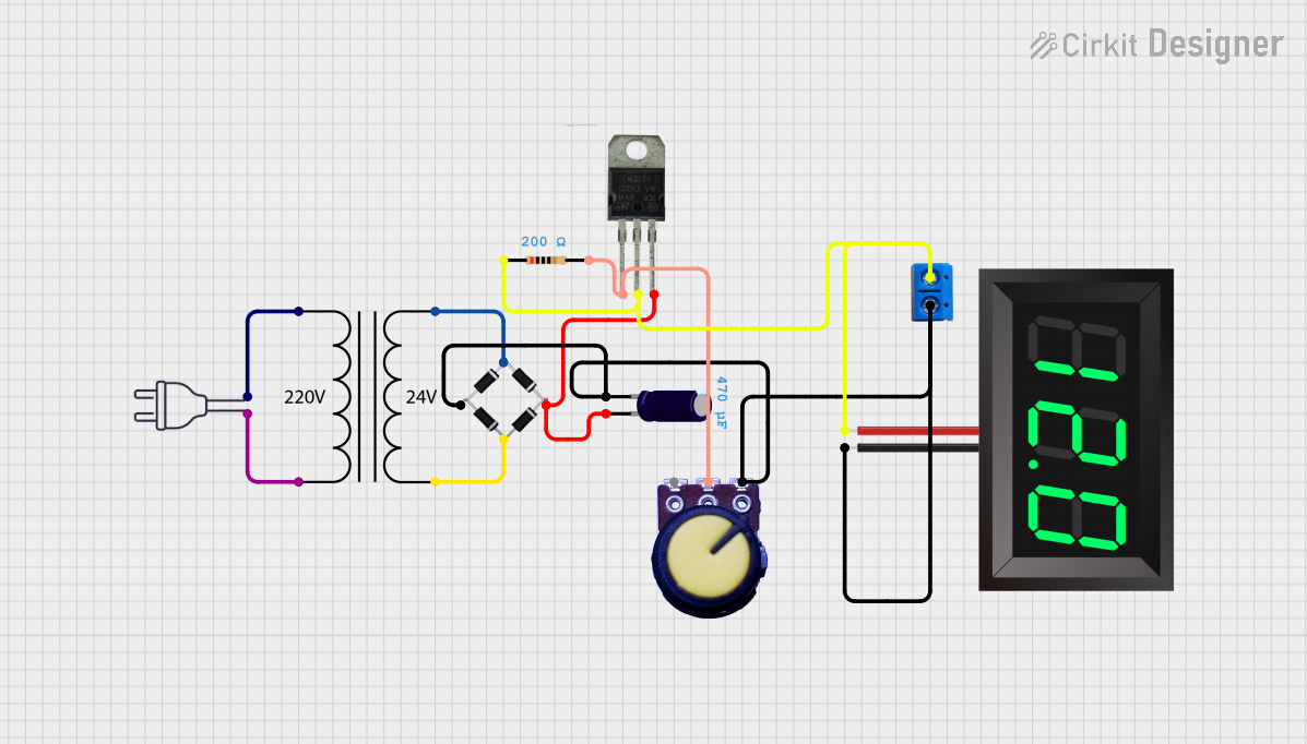
Explore Projects Built with 7-20V to 5V
Common Applications and Use Cases
- Powering microcontrollers like Arduino, ESP32, and Raspberry Pi Pico.
- Supplying 5V to sensors, displays, and communication modules.
- Voltage regulation in battery-powered devices.
- DIY electronics projects requiring a stable 5V power source.
Technical Specifications
Below are the key technical details of the 7-20V to 5V voltage regulator:
| Parameter | Value |
|---|---|
| Input Voltage Range | 7V to 20V |
| Output Voltage | 5V ± 0.1V |
| Maximum Output Current | 1A (typical), 1.5A (peak) |
| Efficiency | Up to 90% (depending on load) |
| Operating Temperature | -40°C to +85°C |
| Dimensions | Varies by model (e.g., 25mm x 15mm) |
Pin Configuration and Descriptions
The voltage regulator typically has three pins or terminals:
| Pin | Name | Description |
|---|---|---|
| 1 | VIN | Input voltage pin. Connect to a DC voltage source between 7V and 20V. |
| 2 | GND | Ground pin. Connect to the ground of the circuit. |
| 3 | VOUT | Output voltage pin. Provides a stable 5V output to power your devices. |
Usage Instructions
How to Use the Component in a Circuit
Connect the Input Voltage (VIN):
Attach the VIN pin to a DC power source with a voltage between 7V and 20V. Ensure the power source can supply sufficient current for your application.Connect the Ground (GND):
Connect the GND pin to the ground of your circuit. This establishes a common reference point for the input and output.Connect the Output Voltage (VOUT):
Use the VOUT pin to power your 5V devices. Ensure the total current draw of connected devices does not exceed the regulator's maximum output current.Add Capacitors (Optional but Recommended):
For improved stability, place a capacitor (e.g., 10µF) across the input (VIN and GND) and another across the output (VOUT and GND). This helps filter noise and maintain a stable voltage.
Important Considerations and Best Practices
- Heat Dissipation: If the regulator is operating near its maximum current rating, it may generate heat. Use a heatsink or ensure proper ventilation to prevent overheating.
- Input Voltage Range: Do not exceed the 20V input limit, as this may damage the regulator.
- Load Current: Ensure the total current draw of connected devices does not exceed the regulator's maximum output current (1A typical, 1.5A peak).
- Polarity: Double-check the polarity of your connections. Reversing the input voltage can damage the regulator.
Example: Using the Voltage Regulator with an Arduino UNO
Below is an example of how to use the 7-20V to 5V voltage regulator to power an Arduino UNO:
Circuit Connections
- Connect a 9V battery to the VIN and GND pins of the regulator.
- Connect the VOUT pin of the regulator to the 5V pin of the Arduino UNO.
- Connect the GND pin of the regulator to the GND pin of the Arduino UNO.
Sample Code
Here is a simple Arduino sketch to blink an LED while powered by the regulator:
// This code blinks an LED connected to pin 13 of the Arduino UNO.
// Ensure the Arduino is powered via the 5V output of the voltage regulator.

void setup() {
  pinMode(13, OUTPUT); // Set pin 13 as an output pin
}

void loop() {
  digitalWrite(13, HIGH); // Turn the LED on
  delay(1000);            // Wait for 1 second
  digitalWrite(13, LOW);  // Turn the LED off
  delay(1000);            // Wait for 1 second
}
Troubleshooting and FAQs
Common Issues and Solutions
No Output Voltage:
- Cause: Incorrect wiring or insufficient input voltage.
- Solution: Verify that the input voltage is within the 7-20V range and that all connections are secure.
Overheating:
- Cause: Excessive current draw or poor ventilation.
- Solution: Reduce the load current or add a heatsink to the regulator.
Output Voltage Fluctuations:
- Cause: Insufficient input voltage or lack of filtering capacitors.
- Solution: Ensure the input voltage is stable and add capacitors across VIN and VOUT.
Regulator Not Working After Connection:
- Cause: Reversed polarity or input voltage exceeding 20V.
- Solution: Check the polarity of your connections and ensure the input voltage is within the specified range.
FAQs
Q: Can I use this regulator to power a Raspberry Pi?
A: No, most Raspberry Pi models require more than 1A of current, which exceeds the typical output capacity of this regulator.
Q: Do I need to use capacitors with this regulator?
A: While not mandatory, adding capacitors improves stability and reduces noise, especially in sensitive applications.
Q: Can I use this regulator with an AC power source?
A: No, this regulator is designed for DC input only. Use a rectifier and filter circuit to convert AC to DC before connecting to the regulator.
Q: What happens if I exceed the input voltage range?
A: Exceeding 20V can permanently damage the regulator. Always ensure the input voltage is within the specified range.