How to Use Bus I2C: Examples, Pinouts, and Specs
Introduction
The Bus I2C (Inter-Integrated Circuit) by Chino is a versatile, multi-master, multi-slave, packet-switched, single-ended serial communication bus. It is widely used for connecting low-speed peripherals to a motherboard, microcontroller, or other devices. The I2C bus is known for its simplicity and efficiency, requiring only two wires for communication: a data line (SDA) and a clock line (SCL).
Explore Projects Built with Bus I2C
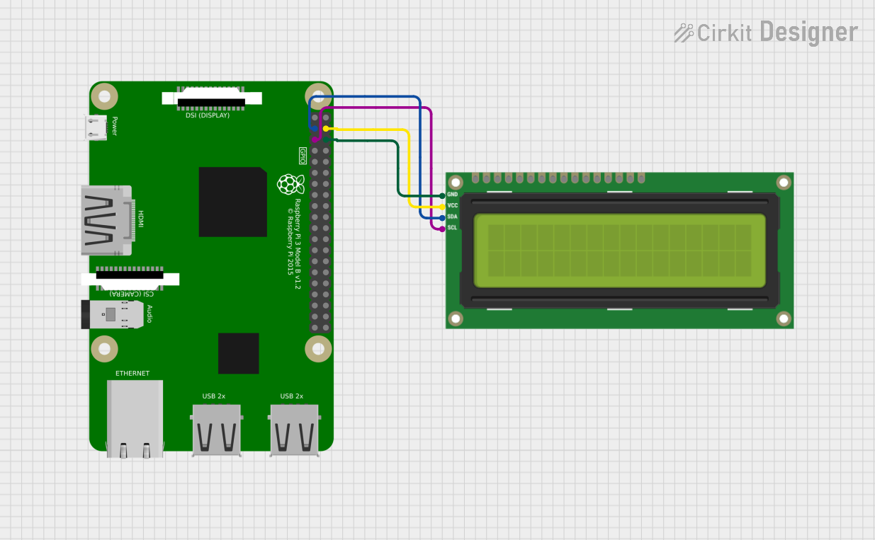

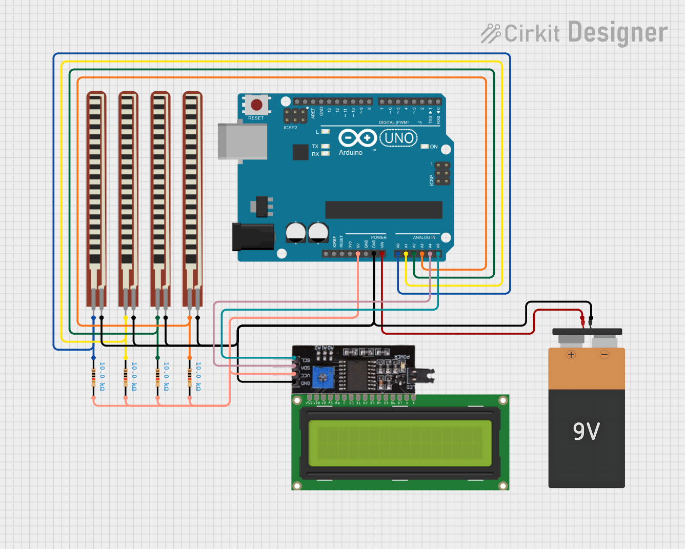
Explore Projects Built with Bus I2C
Common Applications and Use Cases
- Communication between microcontrollers and sensors, displays, or EEPROMs.
- Connecting real-time clocks (RTC) to microcontrollers.
- Interfacing with ADCs (Analog-to-Digital Converters) and DACs (Digital-to-Analog Converters).
- Communication in embedded systems and IoT devices.
- Low-speed data transfer in consumer electronics.
Technical Specifications
The following are the key technical details of the Chino Bus I2C:
General Specifications
- Communication Type: Serial, synchronous
- Number of Wires: 2 (SDA - Serial Data, SCL - Serial Clock)
- Voltage Levels: 3.3V or 5V (depending on the system)
- Data Transfer Rate:
- Standard Mode: Up to 100 kbit/s
- Fast Mode: Up to 400 kbit/s
- Fast Mode Plus: Up to 1 Mbit/s
- High-Speed Mode: Up to 3.4 Mbit/s
- Addressing: 7-bit or 10-bit addressing
- Pull-Up Resistors: Required on both SDA and SCL lines (typical values: 4.7kΩ or 10kΩ)
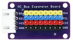
Pin Configuration and Descriptions
The I2C bus uses two primary pins for communication. These pins are described in the table below:
| Pin Name | Description | Direction | Notes |
|---|---|---|---|
| SDA | Serial Data Line | Bidirectional | Requires a pull-up resistor |
| SCL | Serial Clock Line | Input | Requires a pull-up resistor |
| GND | Ground | - | Common ground for all devices |
| VCC | Power Supply (3.3V or 5V) | - | Depends on the system requirements |
Usage Instructions
How to Use the Component in a Circuit
- Connect the SDA and SCL Lines:
- Connect the SDA pin of the I2C master device (e.g., microcontroller) to the SDA pin of the slave device.
- Similarly, connect the SCL pin of the master to the SCL pin of the slave.
- Add Pull-Up Resistors:
- Attach pull-up resistors (typically 4.7kΩ or 10kΩ) to both the SDA and SCL lines. These resistors ensure proper signal levels.
- Power the Devices:
- Provide a common ground (GND) and appropriate power supply (VCC) to all devices on the I2C bus.
- Address the Devices:
- Each slave device on the I2C bus must have a unique address. Configure the address as per the device datasheet.
- Write Code for Communication:
- Use a microcontroller or processor to send and receive data over the I2C bus.
Important Considerations and Best Practices
- Bus Length: Keep the bus length short to avoid signal degradation.
- Pull-Up Resistors: Ensure the pull-up resistor values are appropriate for the bus speed and capacitance.
- Address Conflicts: Avoid address conflicts by assigning unique addresses to each slave device.
- Clock Stretching: Some slave devices may stretch the clock. Ensure the master device supports this feature if required.
- Noise and Interference: Use proper shielding and grounding to minimize noise on the I2C lines.
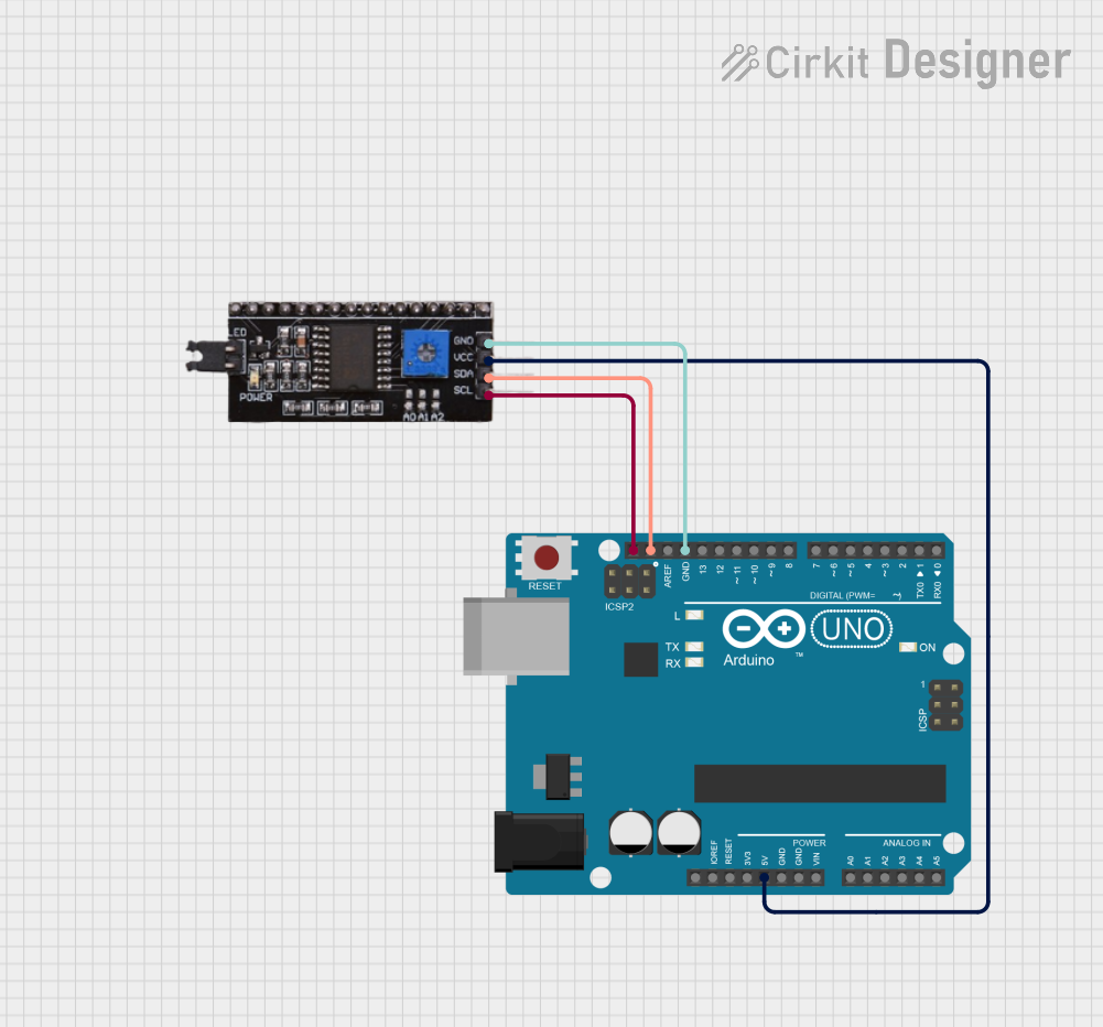
Example: Connecting an I2C Sensor to Arduino UNO
Below is an example of how to connect an I2C temperature sensor to an Arduino UNO and read data:
Circuit Diagram
- Connect the SDA pin of the sensor to A4 (SDA) on the Arduino UNO.
- Connect the SCL pin of the sensor to A5 (SCL) on the Arduino UNO.
- Add 4.7kΩ pull-up resistors to both SDA and SCL lines.
- Power the sensor with 3.3V or 5V, depending on its requirements.
Arduino Code
#include <Wire.h> // Include the Wire library for I2C communication

#define SENSOR_ADDRESS 0x48 // Replace with your sensor's I2C address

void setup() {
  Wire.begin(); // Initialize I2C communication
  Serial.begin(9600); // Start serial communication for debugging
  Serial.println("I2C Sensor Example");
}

void loop() {
  Wire.beginTransmission(SENSOR_ADDRESS); // Start communication with the sensor
  Wire.write(0x00); // Send a command to the sensor (e.g., read temperature)
  Wire.endTransmission(); // End the transmission

  Wire.requestFrom(SENSOR_ADDRESS, 2); // Request 2 bytes of data from the sensor
  if (Wire.available() == 2) { // Check if 2 bytes are available
    int data = Wire.read() << 8 | Wire.read(); // Read and combine the bytes
    float temperature = data * 0.0625; // Convert to temperature (example conversion)
    Serial.print("Temperature: ");
    Serial.print(temperature);
    Serial.println(" °C");
  }

  delay(1000); // Wait for 1 second before the next reading
}
Troubleshooting and FAQs
Common Issues and Solutions
No Communication on the Bus:
- Cause: Missing or incorrect pull-up resistors.
- Solution: Ensure proper pull-up resistors (4.7kΩ or 10kΩ) are connected to SDA and SCL.
Address Conflict:
- Cause: Two devices on the bus have the same address.
- Solution: Check the datasheets and configure unique addresses for each device.
Data Corruption:
- Cause: Excessive noise or long bus length.
- Solution: Shorten the bus length and use proper shielding.
Clock Stretching Issues:
- Cause: The master device does not support clock stretching.
- Solution: Verify that the master device supports clock stretching or use a compatible slave device.
FAQs
Q: Can I connect multiple devices to the same I2C bus?
- A: Yes, multiple devices can share the same SDA and SCL lines as long as each device has a unique address.
Q: What happens if I forget to add pull-up resistors?
- A: The I2C bus will not function correctly, as the lines will not be pulled to a high state.
Q: How do I determine the correct pull-up resistor value?
- A: The value depends on the bus speed and capacitance. A typical value is 4.7kΩ, but you can calculate it using the formula:
R = V/I, whereIis the desired pull-up current.
- A: The value depends on the bus speed and capacitance. A typical value is 4.7kΩ, but you can calculate it using the formula:
Q: Can I use I2C with 3.3V and 5V devices on the same bus?
- A: Yes, but you may need a level shifter to safely interface between the two voltage levels.
This documentation provides a comprehensive guide to using the Chino Bus I2C. For further details, refer to the specific datasheets of the devices you are interfacing with.