How to Use DC Powered Bell: Examples, Pinouts, and Specs
Introduction
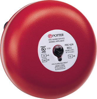
The PDC 10G is a DC-powered bell manufactured by PDC, designed for use in doorbell systems, alert mechanisms, and other signaling applications. This component operates by producing a clear and audible sound when a DC voltage is applied, making it ideal for residential, commercial, and industrial environments. Its simple design and reliable performance make it a popular choice for low-voltage signaling systems.
Explore Projects Built with DC Powered Bell
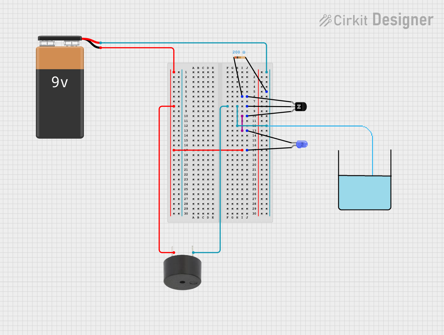
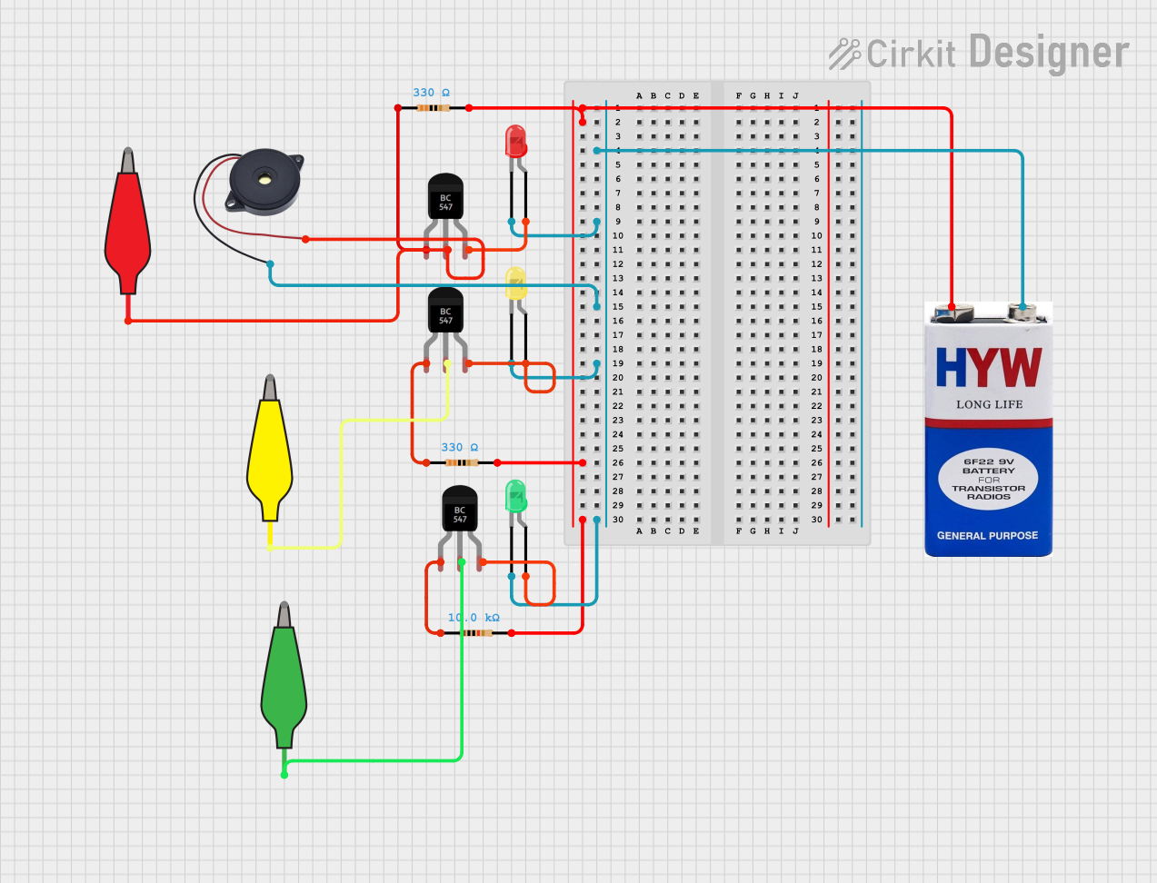
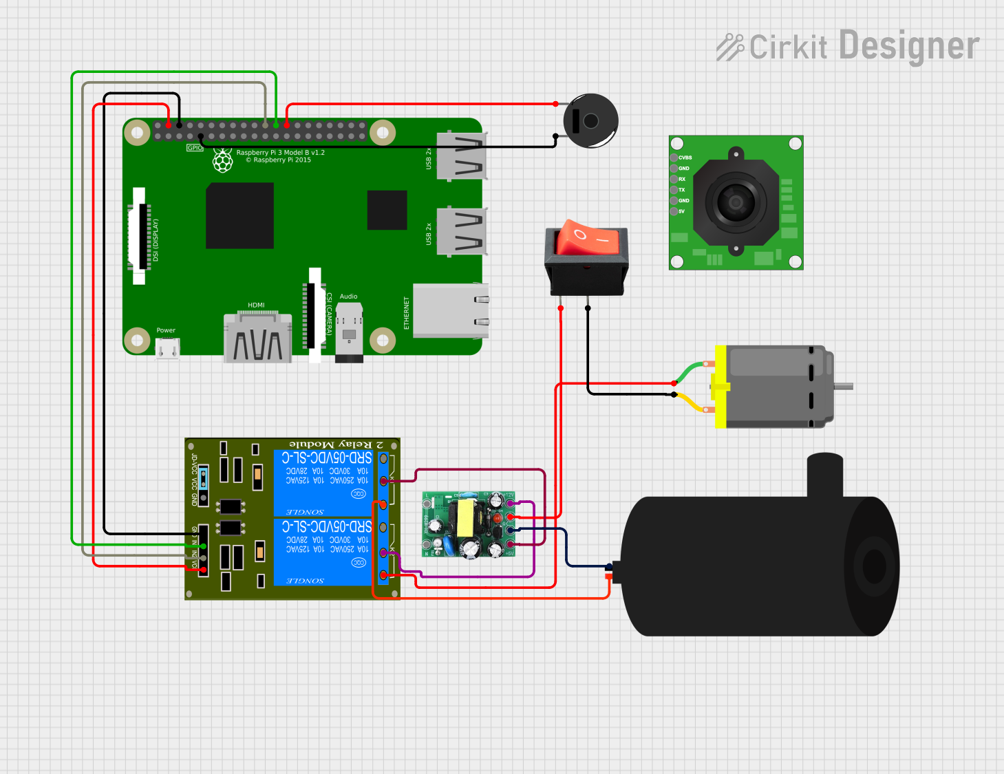
Explore Projects Built with DC Powered Bell
Common Applications and Use Cases
- Doorbell systems in homes and offices
- Alert systems in industrial or commercial setups
- Notification mechanisms in security systems
- Educational or training environments for signaling purposes
Technical Specifications
The following table outlines the key technical details of the PDC 10G DC-powered bell:
| Parameter | Specification |
|---|---|
| Operating Voltage | 6V to 12V DC |
| Current Consumption | 100mA (typical) |
| Sound Output Level | 85 dB at 1 meter |
| Operating Temperature | -10°C to 50°C |
| Dimensions | 70mm x 70mm x 30mm |
| Mounting Type | Surface mount |
| Weight | 120 grams |
Pin Configuration and Descriptions
The PDC 10G has two terminals for electrical connections. The table below describes the pin configuration:
| Pin | Label | Description |
|---|---|---|
| 1 | V+ | Positive terminal for DC power input |
| 2 | GND | Ground terminal for DC power input |
Usage Instructions
How to Use the Component in a Circuit
- Power Supply: Connect the V+ terminal to the positive terminal of a DC power source (6V to 12V). Ensure the power supply is within the specified voltage range to avoid damage.
- Ground Connection: Connect the GND terminal to the negative terminal of the DC power source.
- Activation: When power is applied, the bell will produce a sound. You can control the activation using a switch, relay, or microcontroller.
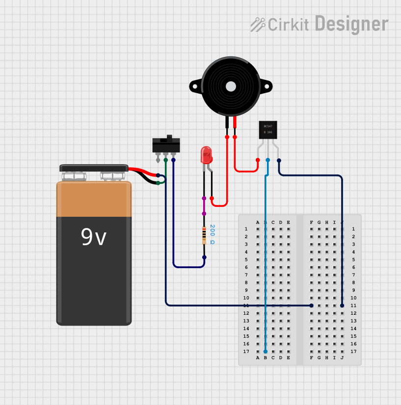
Example Circuit with Arduino UNO
The PDC 10G can be easily integrated with an Arduino UNO for automated control. Below is an example circuit and code to activate the bell using a digital output pin.
Circuit Connections
- Connect the V+ terminal of the bell to the Arduino's digital pin (e.g., pin 8) through a transistor (e.g., 2N2222) for current amplification.
- Connect the GND terminal of the bell to the Arduino's GND.
- Use a 1kΩ resistor between the Arduino's digital pin and the transistor's base.
Arduino Code
// Example code to control the PDC 10G DC-powered bell using Arduino UNO

const int bellPin = 8; // Define the digital pin connected to the bell

void setup() {
  pinMode(bellPin, OUTPUT); // Set the bell pin as an output
}

void loop() {
  digitalWrite(bellPin, HIGH); // Activate the bell
  delay(1000);                 // Keep the bell on for 1 second
  digitalWrite(bellPin, LOW);  // Deactivate the bell
  delay(2000);                 // Wait for 2 seconds before reactivating
}
Important Considerations and Best Practices
- Voltage Range: Always operate the bell within the specified voltage range (6V to 12V DC) to prevent damage.
- Current Handling: Ensure the power supply can provide at least 100mA of current.
- Mounting: Securely mount the bell on a flat surface to avoid vibrations or noise distortion.
- Polarity: Double-check the polarity of the connections to avoid reverse polarity damage.
Troubleshooting and FAQs
Common Issues and Solutions
No Sound from the Bell
- Cause: Incorrect wiring or insufficient power supply.
- Solution: Verify the connections and ensure the power supply provides the required voltage and current.
Weak or Distorted Sound
- Cause: Low voltage or loose mounting.
- Solution: Check the power supply voltage and ensure the bell is securely mounted.
Bell Stays On Continuously
- Cause: Faulty control circuit or stuck switch.
- Solution: Inspect the control circuit and replace any faulty components.
Overheating
- Cause: Prolonged operation or excessive voltage.
- Solution: Operate the bell intermittently and ensure the voltage is within the specified range.
FAQs
Q1: Can the PDC 10G be used with an AC power source?
A1: No, the PDC 10G is designed for DC power only. Using an AC power source may damage the component.
Q2: What is the maximum distance for wiring the bell?
A2: The maximum distance depends on the wire gauge and power supply. For typical applications, use a low-resistance wire and keep the distance under 10 meters to minimize voltage drop.
Q3: Can the bell be used outdoors?
A3: The PDC 10G is not weatherproof. If outdoor use is required, ensure it is housed in a weather-resistant enclosure.
Q4: How can I reduce the sound level of the bell?
A4: You can reduce the sound level by partially covering the bell's sound outlet or using a lower voltage within the operating range.