
How to Use TRRS 3.5mm Jack Breakout: Examples, Pinouts, and Specs
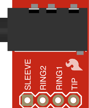
 Design with TRRS 3.5mm Jack Breakout in Cirkit Designer
Introduction
The TRRS 3.5mm Jack Breakout is a compact and versatile breakout board designed for easy integration of a TRRS (Tip-Ring-Ring-Sleeve) 3.5mm audio jack into electronic projects. This component simplifies the process of connecting audio and microphone signals, making it ideal for applications involving headphones, microphones, or other audio devices.
Common applications include:
- Audio input/output for microcontroller projects
- Headphone and microphone interfacing
- DIY audio devices and amplifiers
- Hands-free communication systems
Explore Projects Built with TRRS 3.5mm Jack Breakout
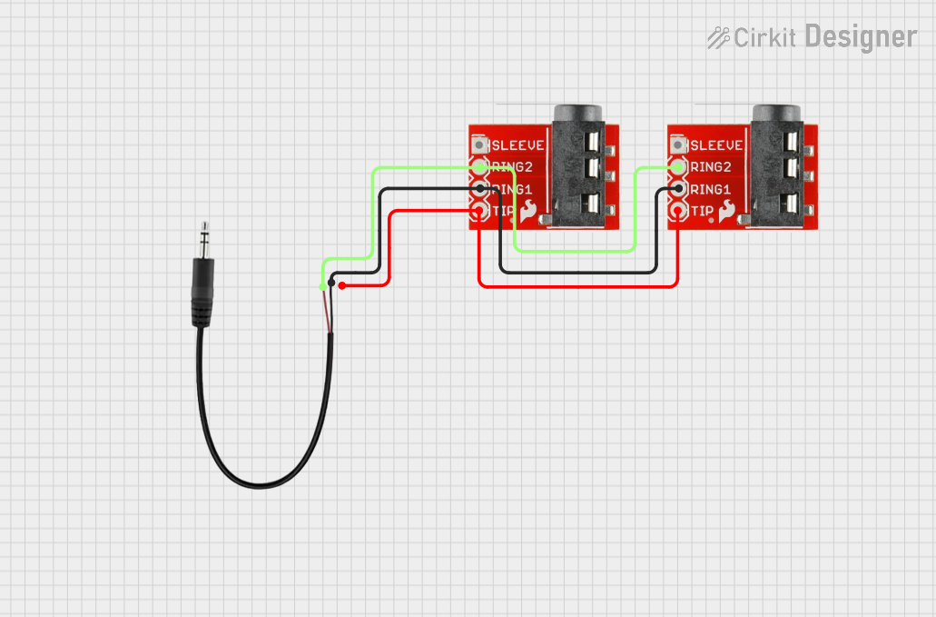 Open Project in Cirkit Designer
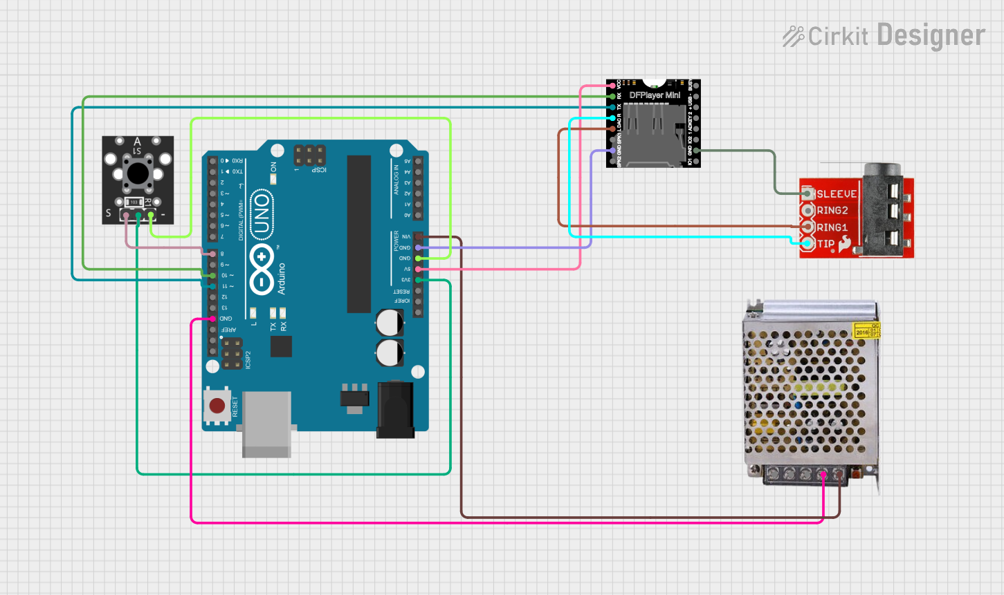 Open Project in Cirkit Designer
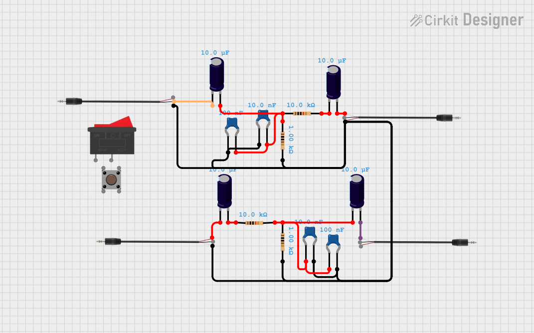 Open Project in Cirkit Designer
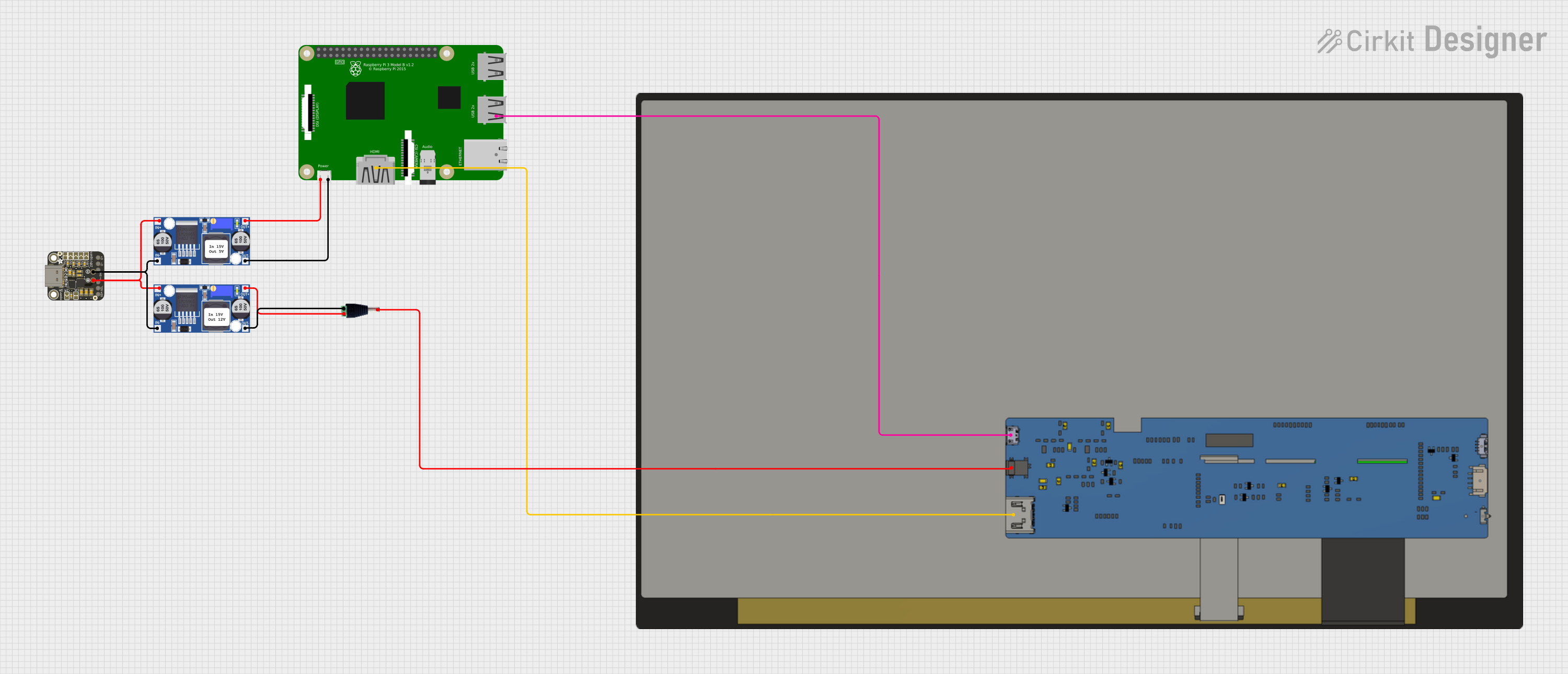 Open Project in Cirkit Designer
Explore Projects Built with TRRS 3.5mm Jack Breakout
Open Project in Cirkit DesignerOpen Project in Cirkit DesignerOpen Project in Cirkit DesignerOpen Project in Cirkit DesignerTechnical Specifications
- Connector Type: TRRS 3.5mm audio jack
- Breakout Pins: Tip, Ring 1, Ring 2, Sleeve
- Voltage Rating: Supports standard audio signal levels (typically 0.5V to 2V peak-to-peak)
- Board Dimensions: Approximately 20mm x 15mm
- Mounting: PCB-mountable with solder pads or headers
- Material: Gold-plated contacts for improved conductivity and durability
Pin Configuration and Descriptions
The TRRS 3.5mm Jack Breakout provides four pins corresponding to the TRRS connector's contacts. The pinout is as follows:
| Pin Name | Description |
|---|---|
| Tip (T) | Left audio channel output/input. |
| Ring 1 (R1) | Right audio channel output/input. |
| Ring 2 (R2) | Microphone input or ground, depending on the wiring standard (CTIA/OMTP). |
| Sleeve (S) | Ground connection. |
Note: The wiring standard (CTIA or OMTP) determines the function of the Ring 2 and Sleeve pins. CTIA is more commonly used in modern devices.
Usage Instructions
How to Use the Component in a Circuit
Connect the Breakout Board:
- Solder header pins or wires to the breakout board's pads for easy connection to your circuit.
- Ensure proper alignment of the TRRS jack with the corresponding pins (Tip, Ring 1, Ring 2, Sleeve).
Determine the Wiring Standard:
- Identify whether your audio device uses the CTIA or OMTP standard.
- For CTIA, Ring 2 is the microphone input, and Sleeve is ground.
- For OMTP, Ring 2 is ground, and Sleeve is the microphone input.
Connect to a Microcontroller or Amplifier:
- Use the Tip and Ring 1 pins for stereo audio signals.
- Connect the Ring 2 pin to the microphone input (if applicable).
- Ensure the Sleeve pin is connected to the ground of your circuit.
Test the Connections:
- Plug in a TRRS-compatible device (e.g., headphones with a microphone).
- Verify audio input/output functionality using appropriate test signals or software.
Important Considerations and Best Practices
- Signal Levels: Ensure that the audio signal levels are within the supported range of your microcontroller or amplifier.
- Wiring Standard: Double-check the wiring standard of your audio device to avoid incorrect connections.
- Shielding: Use shielded cables for audio connections to minimize noise and interference.
- Soldering: Use a fine-tipped soldering iron and avoid excessive heat to prevent damage to the breakout board.
Example: Connecting to an Arduino UNO
Below is an example of how to use the TRRS 3.5mm Jack Breakout with an Arduino UNO to read microphone input:
// Example: Reading microphone input from a TRRS breakout board
// Connect the microphone pin (Ring 2 for CTIA) to Arduino analog pin A0
// Ensure the Sleeve pin is connected to Arduino GND

const int micPin = A0;  // Microphone input pin
int micValue = 0;       // Variable to store microphone signal value

void setup() {
  Serial.begin(9600);  // Initialize serial communication
  pinMode(micPin, INPUT);  // Set the microphone pin as input
}

void loop() {
  micValue = analogRead(micPin);  // Read the microphone signal
  Serial.println(micValue);      // Print the signal value to the Serial Monitor
  delay(100);  // Small delay for readability
}
Note: This example assumes the microphone signal is analog and within the Arduino's input voltage range (0-5V). Use a preamplifier if the signal is too weak.
Troubleshooting and FAQs
Common Issues
No Audio Output:
- Cause: Incorrect wiring or incompatible wiring standard (CTIA/OMTP).
- Solution: Verify the pin connections and ensure the correct wiring standard is used.
Noise or Interference:
- Cause: Unshielded cables or poor grounding.
- Solution: Use shielded cables and ensure a solid ground connection.
Microphone Not Detected:
- Cause: Misconfigured Ring 2 and Sleeve connections.
- Solution: Check the wiring standard and adjust connections accordingly.
Loose Connections:
- Cause: Poor soldering or loose headers.
- Solution: Re-solder the connections or use secure headers.
FAQs
Q: Can I use this breakout board with a mono audio device?
A: Yes, but only the Tip and Sleeve pins will be used for mono audio signals.
Q: How do I identify the wiring standard of my audio device?
A: Refer to the device's documentation or test the connections with a multimeter to determine the function of each pin.
Q: Can this breakout board handle digital audio signals?
A: No, the TRRS breakout board is designed for analog audio signals. Use a digital audio interface for digital signals.
Q: Is this breakout board compatible with Raspberry Pi?
A: Yes, it can be used with Raspberry Pi GPIO pins for audio input/output, provided the signal levels are compatible.
By following this documentation, you can effectively integrate the TRRS 3.5mm Jack Breakout into your audio projects with ease!