
How to Use DB25: Examples, Pinouts, and Specs
 Design with DB25 in Cirkit Designer
Introduction
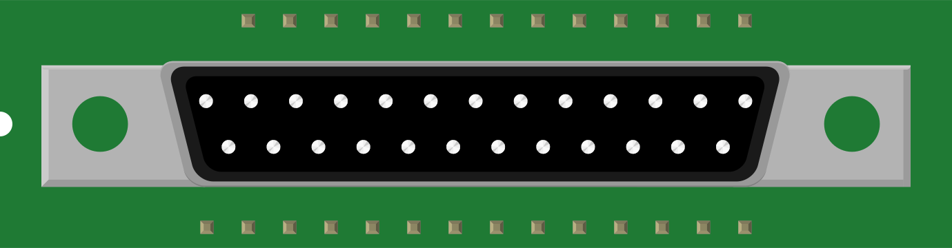
The DB25 is a 25-pin D-subminiature (D-sub) connector widely used for parallel and serial communication. It is characterized by its trapezoidal shape and robust design, making it suitable for a variety of applications. The DB25 connector was historically used in older computer interfaces, such as parallel printer ports and RS-232 serial communication. Despite being less common in modern devices, it remains relevant in legacy systems, industrial equipment, and specialized applications.
Explore Projects Built with DB25
 Open Project in Cirkit Designer
 Open Project in Cirkit Designer
 Open Project in Cirkit Designer
 Open Project in Cirkit Designer
Explore Projects Built with DB25
Open Project in Cirkit DesignerOpen Project in Cirkit DesignerOpen Project in Cirkit DesignerOpen Project in Cirkit DesignerCommon Applications
- Parallel communication (e.g., printer interfaces)
- RS-232 serial communication
- Industrial control systems
- Test and measurement equipment
- Audio and video signal transmission in some setups
Technical Specifications
Key Technical Details
- Connector Type: D-subminiature, 25-pin
- Pin Count: 25
- Gender: Male (plug) or Female (socket)
- Mounting Style: Panel mount or cable mount
- Contact Material: Gold or tin-plated contacts for reliable conductivity
- Current Rating: Typically 5A per pin (varies by manufacturer)
- Voltage Rating: Up to 300V (varies by manufacturer)
- Operating Temperature: -55°C to +105°C (typical)
Pin Configuration and Descriptions
The pinout of the DB25 connector depends on its application. Below are two common configurations: Parallel Port (IEEE 1284) and RS-232 Serial Communication.
Parallel Port Pinout (IEEE 1284 Standard)
| Pin Number | Signal Name | Direction | Description |
|---|---|---|---|
| 1 | Strobe | Output | Data strobe signal |
| 2 | Data 0 | Output | Data bit 0 |
| 3 | Data 1 | Output | Data bit 1 |
| 4 | Data 2 | Output | Data bit 2 |
| 5 | Data 3 | Output | Data bit 3 |
| 6 | Data 4 | Output | Data bit 4 |
| 7 | Data 5 | Output | Data bit 5 |
| 8 | Data 6 | Output | Data bit 6 |
| 9 | Data 7 | Output | Data bit 7 |
| 10 | Acknowledge | Input | Acknowledgment from the device |
| 11 | Busy | Input | Device busy signal |
| 12 | Paper Out | Input | Paper out signal (printers) |
| 13 | Select | Input | Device select signal |
| 14 | Auto Feed | Output | Auto feed signal |
| 15 | Error | Input | Error signal from the device |
| 16 | Initialize | Output | Initialize the device |
| 17 | Select In | Output | Select input signal |
| 18-25 | Ground | - | Signal ground |
RS-232 Serial Communication Pinout
| Pin Number | Signal Name | Direction | Description |
|---|---|---|---|
| 1 | Shield Ground | - | Protective ground |
| 2 | Transmit Data (TD) | Output | Data transmitted from DTE |
| 3 | Receive Data (RD) | Input | Data received by DTE |
| 4 | Request to Send | Output | Flow control signal |
| 5 | Clear to Send | Input | Flow control signal |
| 6 | Data Set Ready | Input | Indicates readiness of DCE |
| 7 | Signal Ground | - | Common ground |
| 8 | Carrier Detect | Input | Detects carrier signal |
| 9 | Reserved | - | Reserved for future use |
| 10-25 | Not Used | - | Unused pins |
Usage Instructions
How to Use the DB25 in a Circuit
- Identify the Application: Determine whether the DB25 will be used for parallel or serial communication, as the pinout and wiring will differ.
- Choose the Correct Gender: Use a male connector for the plug and a female connector for the socket.
- Wiring:
- For parallel communication, connect the data pins (2-9) to the corresponding device inputs/outputs.
- For RS-232, connect the transmit (pin 2) and receive (pin 3) lines appropriately, ensuring proper grounding (pin 7).
- Soldering: If using a solder-type DB25 connector, carefully solder wires to the appropriate pins. Use heat shrink tubing to insulate connections.
- Mounting: Secure the connector to a panel or enclosure using screws or clips to ensure a stable connection.
Important Considerations
- Signal Integrity: Use shielded cables to minimize electromagnetic interference (EMI), especially for long cable runs.
- Voltage Levels: Ensure the voltage levels on the pins match the specifications of the connected devices.
- Legacy Systems: Be aware that modern devices may not natively support DB25 connectors, requiring adapters or converters.
Example: Connecting DB25 to Arduino UNO
The DB25 can be interfaced with an Arduino UNO for basic communication. Below is an example of reading data from a DB25 parallel port.
// Example: Reading data from a DB25 parallel port using Arduino UNO
// Connect DB25 pins 2-9 (data lines) to Arduino digital pins 2-9
// Connect DB25 pin 18 (ground) to Arduino GND

void setup() {
  // Set Arduino pins 2-9 as inputs
  for (int pin = 2; pin <= 9; pin++) {
    pinMode(pin, INPUT);
  }
  Serial.begin(9600); // Initialize serial communication
}

void loop() {
  byte data = 0; // Variable to store the 8-bit data

  // Read data from DB25 pins 2-9
  for (int pin = 2; pin <= 9; pin++) {
    data |= (digitalRead(pin) << (pin - 2)); // Shift and combine bits
  }

  Serial.println(data, BIN); // Print the data in binary format
  delay(500); // Delay for readability
}
Troubleshooting and FAQs
Common Issues
No Signal Detected:
- Cause: Incorrect wiring or loose connections.
- Solution: Double-check the pinout and ensure all connections are secure.
Interference or Noise:
- Cause: Unshielded cables or long cable runs.
- Solution: Use shielded cables and keep cable lengths as short as possible.
Device Not Responding:
- Cause: Incorrect pin configuration or mismatched voltage levels.
- Solution: Verify the pinout and ensure voltage levels are compatible.
Overheating:
- Cause: Exceeding current or voltage ratings.
- Solution: Ensure the connected devices do not exceed the DB25's specifications.
FAQs
Q: Can I use a DB25 connector for modern devices?
- A: Yes, but you may need adapters or converters, as most modern devices use USB or other interfaces.
Q: How do I identify the pin numbers on a DB25 connector?
- A: Pin numbers are typically labeled on the connector housing. If not, refer to the pinout diagrams provided above.
Q: Is the DB25 connector still relevant today?
- A: While less common in consumer electronics, it is still widely used in industrial and legacy systems.
Q: Can I use the DB25 for custom applications?
- A: Absolutely! The DB25's versatility makes it suitable for various custom projects, including data transfer and control systems.