How to Use Power Multiplexer: Examples, Pinouts, and Specs
Introduction
The TPS2113A, manufactured by Texas Instruments, is a power multiplexer designed to seamlessly switch between two power sources to supply a single output. This device ensures reliable power delivery by automatically selecting the most suitable power source based on priority or availability. It is particularly useful in applications requiring redundancy or uninterrupted power supply.
Explore Projects Built with Power Multiplexer


Explore Projects Built with Power Multiplexer
Common Applications and Use Cases
- Battery-powered devices with USB charging
- Systems requiring automatic power source selection (e.g., USB vs. battery)
- Portable electronics with dual power inputs
- Embedded systems and microcontroller-based designs
- Power redundancy in critical systems
Technical Specifications
The TPS2113A is a highly versatile power multiplexer with the following key specifications:
| Parameter | Value |
|---|---|
| Input Voltage Range | 2.8 V to 5.5 V |
| Output Voltage Range | 2.8 V to 5.5 V |
| Maximum Output Current | 1.25 A |
| Switch-Over Time | 50 µs (typical) |
| Control Logic | Automatic or manual selection |
| Quiescent Current | 55 µA (typical) |
| Operating Temperature Range | -40°C to 85°C |
| Package Type | 8-pin VSSOP |
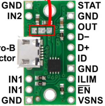
Pin Configuration and Descriptions
The TPS2113A is available in an 8-pin VSSOP package. The pinout and descriptions are as follows:
| Pin Number | Pin Name | Description |
|---|---|---|
| 1 | IN1 | Power input 1 (primary power source) |
| 2 | IN2 | Power input 2 (secondary power source) |
| 3 | GND | Ground connection |
| 4 | OUT | Output voltage (connected to the selected power source) |
| 5 | CTL | Control pin for manual source selection (logic high or low) |
| 6 | PR1 | Priority input for IN1 (logic high gives IN1 higher priority over IN2) |
| 7 | PR2 | Priority input for IN2 (logic high gives IN2 higher priority over IN1) |
| 8 | EN | Enable pin (logic high enables the device, logic low disables it) |
Usage Instructions
The TPS2113A is straightforward to use in a circuit. Below are the steps and considerations for proper implementation:
Basic Circuit Connection
- Connect Power Sources:
- Connect the primary power source to the
IN1pin. - Connect the secondary power source to the
IN2pin.
- Connect the primary power source to the
- Output Connection:
- Connect the load to the
OUTpin.
- Connect the load to the
- Control Logic:
- Use the
CTLpin to manually select the power source if needed. - Configure the
PR1andPR2pins to set the priority betweenIN1andIN2.
- Use the
- Enable the Device:
- Pull the
ENpin high to enable the device.
- Pull the
Important Considerations
- Ensure that the input voltages on
IN1andIN2are within the specified range (2.8 V to 5.5 V). - Use appropriate decoupling capacitors (e.g., 1 µF to 10 µF) on the input and output pins to ensure stable operation.
- Avoid exceeding the maximum output current of 1.25 A to prevent damage to the device.
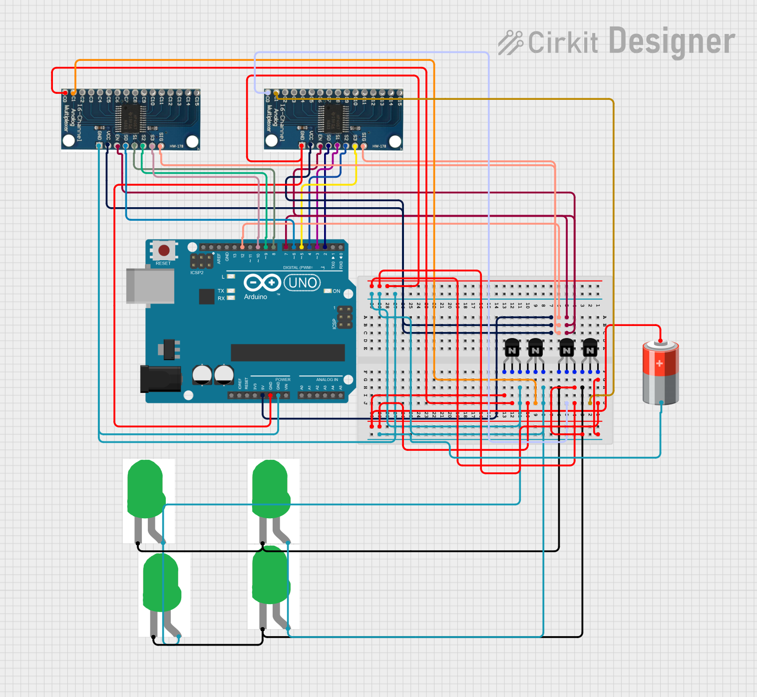
- If using the device with a microcontroller (e.g., Arduino UNO), ensure proper logic level compatibility for control pins.
Example: Using TPS2113A with Arduino UNO
Below is an example of how to control the TPS2113A using an Arduino UNO to manually select the power source:
// Define control pins for TPS2113A
const int ctlPin = 7;  // Connected to CTL pin of TPS2113A
const int enPin = 8;   // Connected to EN pin of TPS2113A

void setup() {
  // Initialize pins as outputs
  pinMode(ctlPin, OUTPUT);
  pinMode(enPin, OUTPUT);

  // Enable the TPS2113A
  digitalWrite(enPin, HIGH);  // Set EN pin high to enable the device
}

void loop() {
  // Example: Switch between power sources every 5 seconds
  digitalWrite(ctlPin, HIGH);  // Select IN1 as the power source
  delay(5000);                 // Wait for 5 seconds

  digitalWrite(ctlPin, LOW);   // Select IN2 as the power source
  delay(5000);                 // Wait for 5 seconds
}
Troubleshooting and FAQs
Common Issues and Solutions
No Output Voltage:
- Ensure the
ENpin is pulled high to enable the device. - Verify that the input voltages on
IN1andIN2are within the specified range. - Check for proper connections and ensure the load is not drawing more than 1.25 A.
- Ensure the
Unstable Output Voltage:
- Add decoupling capacitors (1 µF to 10 µF) to the input and output pins.
- Verify that the input power sources are stable and not fluctuating.
Incorrect Power Source Selection:
- Check the logic levels on the
CTL,PR1, andPR2pins. - Ensure the control signals are properly configured for the desired behavior.
- Check the logic levels on the
FAQs
Q: Can the TPS2113A handle higher output currents?
A: No, the maximum output current is 1.25 A. Exceeding this limit may damage the device.
Q: What happens if both power sources are unavailable?
A: The output will be disabled, and no voltage will be supplied to the load.
Q: Can I use the TPS2113A with a 12 V power source?
A: No, the input voltage range is limited to 2.8 V to 5.5 V. Using a higher voltage may damage the device.
Q: How fast does the TPS2113A switch between power sources?
A: The typical switch-over time is 50 µs, ensuring minimal disruption to the load.
By following the guidelines and recommendations in this documentation, you can effectively integrate the TPS2113A power multiplexer into your designs for reliable and efficient power management.