How to Use Darlington Driver: Examples, Pinouts, and Specs
Introduction
A Darlington Driver is an integrated circuit designed to control high-current loads such as relays, lamps, solenoids, and motors. It leverages the Darlington pair configuration, where two or more bipolar transistors are connected to amplify the current. This configuration allows a small input current to switch a much larger output current, making it ideal for interfacing with microcontrollers and other logic devices.
Explore Projects Built with Darlington Driver
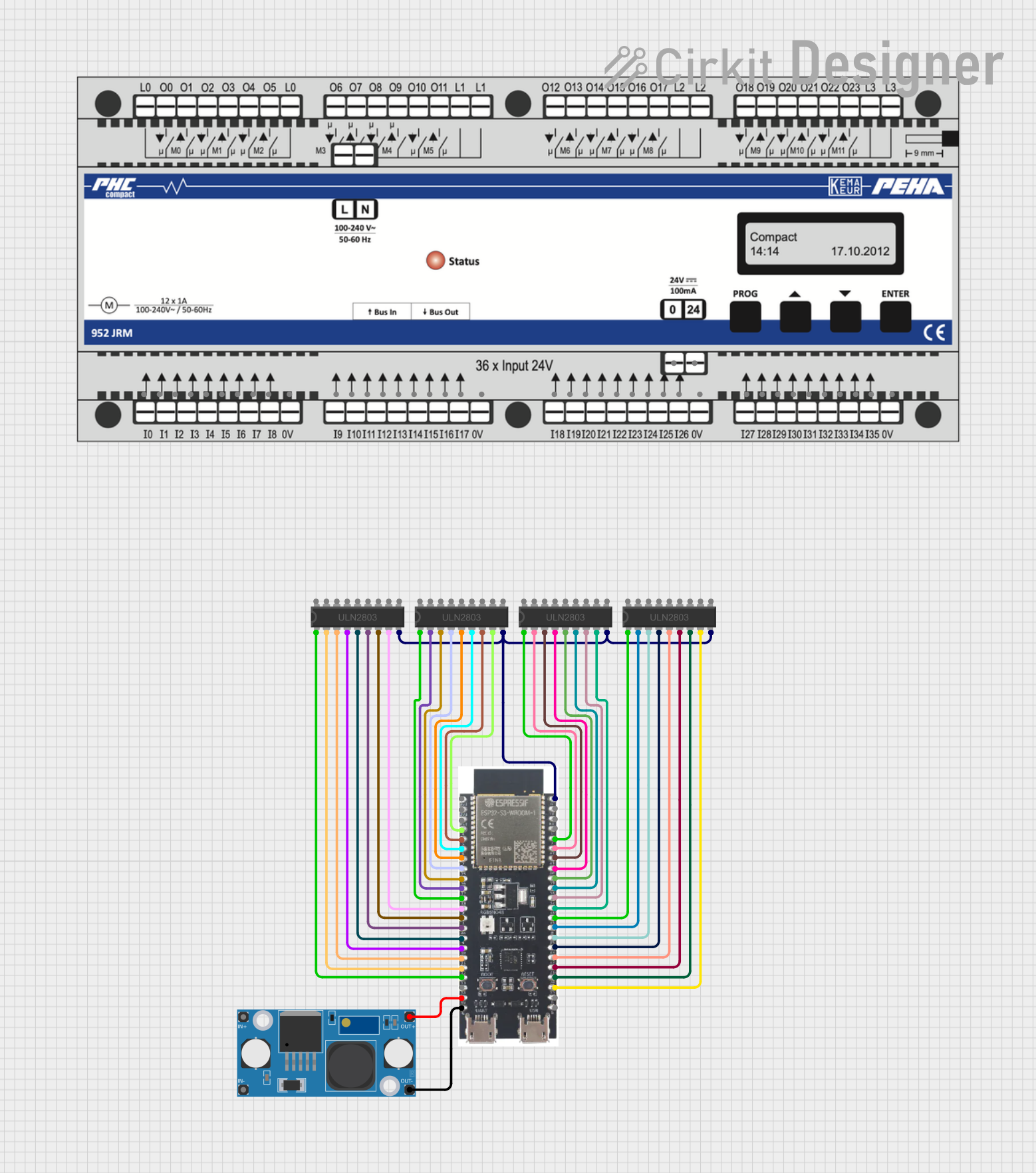
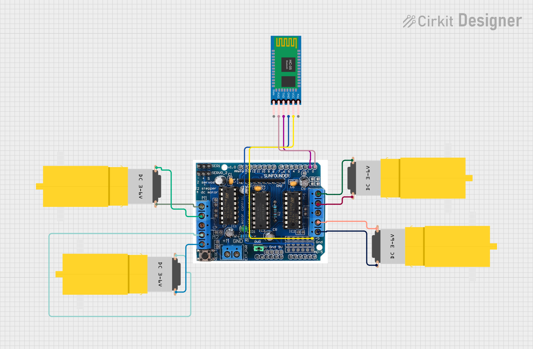
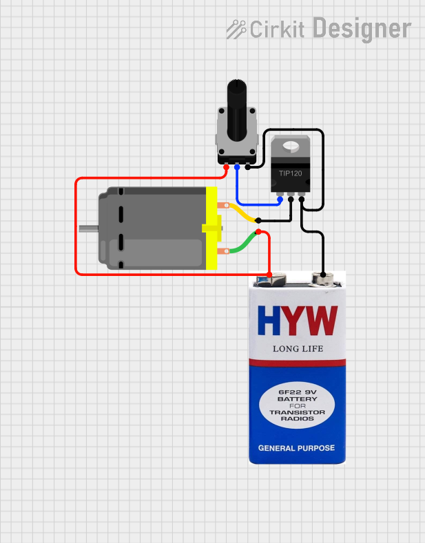
Explore Projects Built with Darlington Driver
Common Applications and Use Cases
- Driving stepper motors in 3D printers and CNC machines
- Controlling relays in home automation systems
- Switching incandescent or high-power LED lighting
- Activating solenoids in vending machines or electronic locks
Technical Specifications
Key Technical Details
- Input Voltage Range: Typically 3.3V to 5V (logic level compatible)
- Output Current: Up to several amperes, depending on the specific model
- Voltage Drop: Varies with load current, typically 1-2V when saturated
- Switching Speed: Suitable for low to moderate speed applications
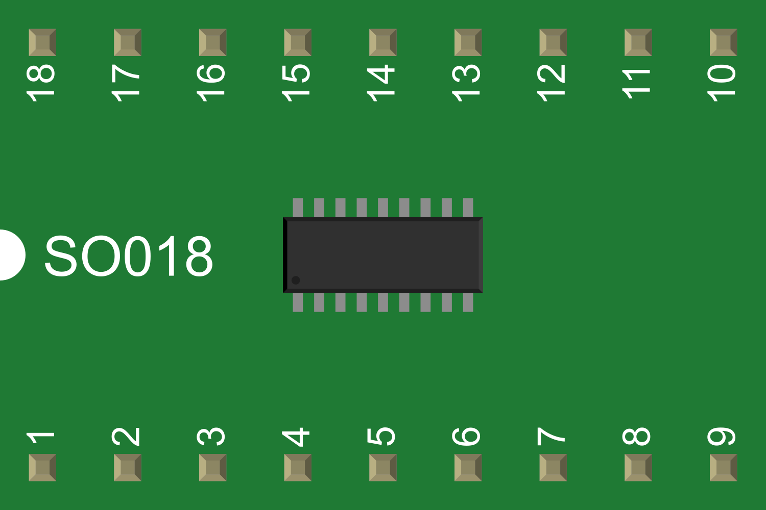
Pin Configuration and Descriptions
| Pin Number | Name | Description |
|---|---|---|
| 1 | IN1 | Input signal for Channel 1 |
| 2 | OUT1 | Output for Channel 1 |
| 3 | IN2 | Input signal for Channel 2 |
| 4 | OUT2 | Output for Channel 2 |
| ... | ... | ... |
| N-1 | INn | Input signal for Channel n |
| N | OUTn | Output for Channel n |
| N+1 | GND | Ground connection |
| N+2 | COM | Common connection for all outputs (if applicable) |
| N+3 | Vcc | Supply voltage for the driver IC |
Note: The actual pin configuration may vary depending on the specific Darlington Driver IC model. Always refer to the manufacturer's datasheet for exact details.
Usage Instructions
How to Use the Component in a Circuit
- Connect the input pins (IN1, IN2, ..., INn) to the control signals, typically from a microcontroller or logic circuit.
- Connect the output pins (OUT1, OUT2, ..., OUTn) to the loads you wish to drive.
- Connect the common ground (GND) to the system ground.
- If available, connect the COM pin to the positive side of the load's power supply.
- Apply the supply voltage (Vcc) to power the driver IC.
Important Considerations and Best Practices
- Ensure the supply voltage (Vcc) and the input signal levels are compatible with the logic levels of the control source.
- Use flyback diodes across inductive loads to protect the driver from voltage spikes.
- Avoid exceeding the maximum rated current to prevent damage to the driver.
- Provide adequate heat sinking if operating near the maximum current rating.
- Implement proper decoupling capacitors close to the Vcc pin to stabilize the supply voltage.
Troubleshooting and FAQs
Common Issues Users Might Face
- Insufficient Drive Current: Ensure the Darlington Driver is rated for the current required by the load.
- Overheating: Check for proper heat sinking and current ratings.
- Unexpected Operation: Verify the input signal integrity and the absence of noise.
Solutions and Tips for Troubleshooting
- If the load does not activate, check the input signal voltage and the supply voltage.
- For inductive loads, ensure flyback diodes are in place to prevent back EMF damage.
- Measure the voltage drop across the output to ensure it is within specifications.
FAQs
Q: Can I drive a load that requires a higher voltage than Vcc? A: Yes, as long as the COM pin (if available) is connected to the load's power supply and does not exceed the maximum voltage rating of the IC.
Q: How can I increase the current handling capability? A: You can parallel multiple outputs if the IC supports it, but ensure proper current sharing and heat management.
Q: Can I use PWM with a Darlington Driver? A: Yes, but the switching speed may limit the maximum PWM frequency. Check the datasheet for frequency specifications.
Example Code for Arduino UNO
// Define the pin connected to the Darlington Driver
const int darlingtonPin = 2;

void setup() {
  // Set the Darlington Driver pin as an output
  pinMode(darlingtonPin, OUTPUT);
}

void loop() {
  // Turn on the connected load
  digitalWrite(darlingtonPin, HIGH);
  delay(1000); // Wait for 1 second

  // Turn off the connected load
  digitalWrite(darlingtonPin, LOW);
  delay(1000); // Wait for 1 second
}
Note: The above code is a simple example to switch a load on and off using an Arduino UNO. Always ensure that the connected load does not exceed the Darlington Driver's specifications.