Cirkit Designer Logo
Cirkit Designer
Your all-in-one circuit design IDE
Home / 
Component Documentation

How to Use Nano Supermini: Examples, Pinouts, and Specs

Image of Nano Supermini
Cirkit Designer LogoDesign with Nano Supermini in Cirkit Designer

Introduction

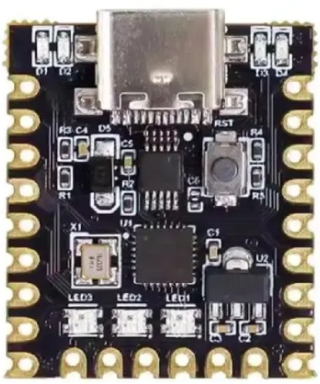
The Nano Supermini is a compact and lightweight microcontroller board developed by Arduino. It is specifically designed for small-scale projects where space and power efficiency are critical. Despite its small size, the Nano Supermini offers versatile connectivity options and robust performance, making it an excellent choice for hobbyists, students, and professionals alike.

Explore Projects Built with Nano Supermini

Use Cirkit Designer to design, explore, and prototype these projects online. Some projects support real-time simulation. Click "Open Project" to start designing instantly!
Beelink Mini S12 N95 and Arduino UNO Based Fingerprint Authentication System with ESP32 CAM
Image of design 3: A project utilizing Nano Supermini in a practical application
This circuit features a Beelink MINI S12 N95 computer connected to a 7-inch display via HDMI for video output and two USB connections for power and touch screen functionality. An Arduino UNO is interfaced with a fingerprint scanner for biometric input. The Beelink MINI S12 N95 is powered by a PC power supply, which in turn is connected to a 240V power source. Additionally, an ESP32 CAM module is powered and programmed via a USB plug and an FTDI programmer, respectively, for wireless camera capabilities.
Cirkit Designer LogoOpen Project in Cirkit Designer
Raspberry Pi Pico-Based Navigation System with Bluetooth and GPS
Image of sat_dish: pwm application: A project utilizing Nano Supermini in a practical application
This circuit features a Raspberry Pi Pico microcontroller interfaced with multiple peripherals for navigation and control. It includes an HC-05 Bluetooth module for wireless communication, an HMC5883L compass for magnetic heading detection, a GPS NEO 6M module for location tracking, and an SG90 servomotor for actuation. The Pico manages data exchange with the GPS and compass via serial connections, controls the servomotor, and communicates wirelessly through the HC-05 module.
Cirkit Designer LogoOpen Project in Cirkit Designer
ESP32C3 Supermini-Based Smart Environment Monitor and Lighting Control System
Image of Bedside RGB and Lamp: A project utilizing Nano Supermini in a practical application
This is a smart control system featuring an ESP32C3 Supermini microcontroller for interfacing with various sensors and actuators. It includes temperature and humidity sensing, RGB LED strip control, user input via a pushbutton and rotary encoder, and AC power control through a two-channel relay. The system is powered by an AC source converted to DC by the HLK-PM12 module.
Cirkit Designer LogoOpen Project in Cirkit Designer
Raspberry Pi Pico-Based Navigation Assistant with Bluetooth and GPS
Image of sat_dish: compass example: A project utilizing Nano Supermini in a practical application
This circuit features a Raspberry Pi Pico microcontroller interfaced with an HC-05 Bluetooth module for wireless communication, an HMC5883L compass module for magnetic field measurement, and a GPS NEO 6M module for location tracking. The Pico is configured to communicate with the HC-05 via serial connection (TX/RX), with the compass module via I2C (SCL/SDA), and with the GPS module via serial (TX/RX). Common power (VCC) and ground (GND) lines are shared among all modules, indicating a unified power system.
Cirkit Designer LogoOpen Project in Cirkit Designer

Explore Projects Built with Nano Supermini

Use Cirkit Designer to design, explore, and prototype these projects online. Some projects support real-time simulation. Click "Open Project" to start designing instantly!
Image of design 3: A project utilizing Nano Supermini in a practical application
Beelink Mini S12 N95 and Arduino UNO Based Fingerprint Authentication System with ESP32 CAM
This circuit features a Beelink MINI S12 N95 computer connected to a 7-inch display via HDMI for video output and two USB connections for power and touch screen functionality. An Arduino UNO is interfaced with a fingerprint scanner for biometric input. The Beelink MINI S12 N95 is powered by a PC power supply, which in turn is connected to a 240V power source. Additionally, an ESP32 CAM module is powered and programmed via a USB plug and an FTDI programmer, respectively, for wireless camera capabilities.
Cirkit Designer LogoOpen Project in Cirkit Designer
Image of sat_dish: pwm application: A project utilizing Nano Supermini in a practical application
Raspberry Pi Pico-Based Navigation System with Bluetooth and GPS
This circuit features a Raspberry Pi Pico microcontroller interfaced with multiple peripherals for navigation and control. It includes an HC-05 Bluetooth module for wireless communication, an HMC5883L compass for magnetic heading detection, a GPS NEO 6M module for location tracking, and an SG90 servomotor for actuation. The Pico manages data exchange with the GPS and compass via serial connections, controls the servomotor, and communicates wirelessly through the HC-05 module.
Cirkit Designer LogoOpen Project in Cirkit Designer
Image of Bedside RGB and Lamp: A project utilizing Nano Supermini in a practical application
ESP32C3 Supermini-Based Smart Environment Monitor and Lighting Control System
This is a smart control system featuring an ESP32C3 Supermini microcontroller for interfacing with various sensors and actuators. It includes temperature and humidity sensing, RGB LED strip control, user input via a pushbutton and rotary encoder, and AC power control through a two-channel relay. The system is powered by an AC source converted to DC by the HLK-PM12 module.
Cirkit Designer LogoOpen Project in Cirkit Designer
Image of sat_dish: compass example: A project utilizing Nano Supermini in a practical application
Raspberry Pi Pico-Based Navigation Assistant with Bluetooth and GPS
This circuit features a Raspberry Pi Pico microcontroller interfaced with an HC-05 Bluetooth module for wireless communication, an HMC5883L compass module for magnetic field measurement, and a GPS NEO 6M module for location tracking. The Pico is configured to communicate with the HC-05 via serial connection (TX/RX), with the compass module via I2C (SCL/SDA), and with the GPS module via serial (TX/RX). Common power (VCC) and ground (GND) lines are shared among all modules, indicating a unified power system.
Cirkit Designer LogoOpen Project in Cirkit Designer

Common Applications and Use Cases

  • Wearable electronics
  • IoT (Internet of Things) devices
  • Portable data loggers
  • Robotics and automation
  • Prototyping small-scale embedded systems

Technical Specifications

The Nano Supermini is built to deliver reliable performance in a compact form factor. Below are its key technical details:

Specification Details
Microcontroller ATmega328P
Operating Voltage 5V
Input Voltage (VIN) 7-12V
Digital I/O Pins 14 (6 PWM outputs)
Analog Input Pins 8
Flash Memory 32 KB (2 KB used by bootloader)
SRAM 2 KB
EEPROM 1 KB
Clock Speed 16 MHz
Dimensions 18 x 45 mm
Weight 7 grams

Pin Configuration and Descriptions

The Nano Supermini features a total of 30 pins, including power, digital, and analog pins. Below is the pinout description:

Pin Type Description
VIN Power Input External power input (7-12V).
GND Ground Ground connection.
5V Power Output Regulated 5V output.
3.3V Power Output Regulated 3.3V output.
A0-A7 Analog Input Analog input pins (10-bit resolution).
D0-D13 Digital I/O Digital input/output pins.
PWM Pins Digital I/O D3, D5, D6, D9, D10, D11 support PWM output.
TX (D1) UART TX Transmit pin for serial communication.
RX (D0) UART RX Receive pin for serial communication.
RESET Reset Resets the microcontroller.

Usage Instructions

The Nano Supermini is easy to integrate into a variety of projects. Follow these steps to get started:

Step 1: Powering the Board

  • The board can be powered via the USB port or an external power source through the VIN pin.
  • Ensure the input voltage is within the range of 7-12V when using the VIN pin.

Step 2: Programming the Board

  • Connect the Nano Supermini to your computer using a USB cable.
  • Open the Arduino IDE and select Tools > Board > Arduino Nano.
  • Choose the correct port under Tools > Port.
  • Write or load your program and click the Upload button.

Step 3: Connecting Components

  • Use the digital and analog pins to connect sensors, actuators, and other peripherals.
  • For PWM control, use pins D3, D5, D6, D9, D10, or D11.

Example: Blinking an LED

Here is a simple example to blink an LED connected to pin D13:

// This program blinks an LED connected to pin D13 on the Nano Supermini.

void setup() {
  pinMode(13, OUTPUT); // Set pin D13 as an output pin
}

void loop() {
  digitalWrite(13, HIGH); // Turn the LED on
  delay(1000);            // Wait for 1 second
  digitalWrite(13, LOW);  // Turn the LED off
  delay(1000);            // Wait for 1 second
}

Important Considerations

  • Avoid exceeding the maximum current rating of the pins (40mA per pin).
  • Use appropriate resistors when connecting LEDs or other components to prevent damage.
  • Ensure proper grounding for stable operation.

Troubleshooting and FAQs

Common Issues and Solutions

  1. The board is not detected by the computer.

    • Ensure the USB cable is functional and properly connected.
    • Install the necessary drivers for the Nano Supermini in the Arduino IDE.
  2. Program upload fails.

    • Verify the correct board and port are selected in the Arduino IDE.
    • Press the reset button on the board before uploading the program.
  3. The board overheats.

    • Check for short circuits in your circuit connections.
    • Ensure the input voltage does not exceed the recommended range.
  4. Analog readings are unstable.

    • Use a capacitor between the analog input pin and ground to filter noise.
    • Ensure proper grounding of all components in the circuit.

FAQs

Q: Can the Nano Supermini run on battery power?
A: Yes, the board can be powered using a battery connected to the VIN pin, provided the voltage is between 7-12V.

Q: Is the Nano Supermini compatible with Arduino shields?
A: Due to its compact size, the Nano Supermini is not directly compatible with standard Arduino shields. However, it can be used with custom shields or breakout boards.

Q: How do I reset the board?
A: Press the reset button on the board, or connect the RESET pin to GND momentarily.

Q: Can I use the Nano Supermini for wireless communication?
A: Yes, you can connect external wireless modules (e.g., Bluetooth, Wi-Fi) to the board via its digital or UART pins.

By following this documentation, you can effectively utilize the Nano Supermini in your projects. Happy tinkering!