
How to Use SmartElex 15S DC Motor Driver 15A (30A Peak) (Single Motor, PWM): Examples, Pinouts, and Specs
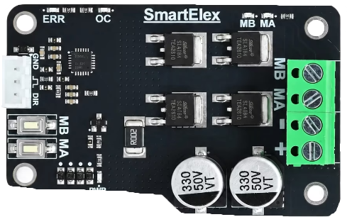
 Design with SmartElex 15S DC Motor Driver 15A (30A Peak) (Single Motor, PWM) in Cirkit Designer
Introduction
The SmartElex 15S DC Motor Driver is a high-performance motor driver designed to control a single DC motor with precision and efficiency. It supports a continuous current rating of 15A and a peak current of 30A, making it ideal for demanding applications. The driver uses Pulse Width Modulation (PWM) for smooth and efficient speed control. Its robust design and versatile features make it suitable for robotics, automation systems, electric vehicles, and other motor control applications.
Explore Projects Built with SmartElex 15S DC Motor Driver 15A (30A Peak) (Single Motor, PWM)
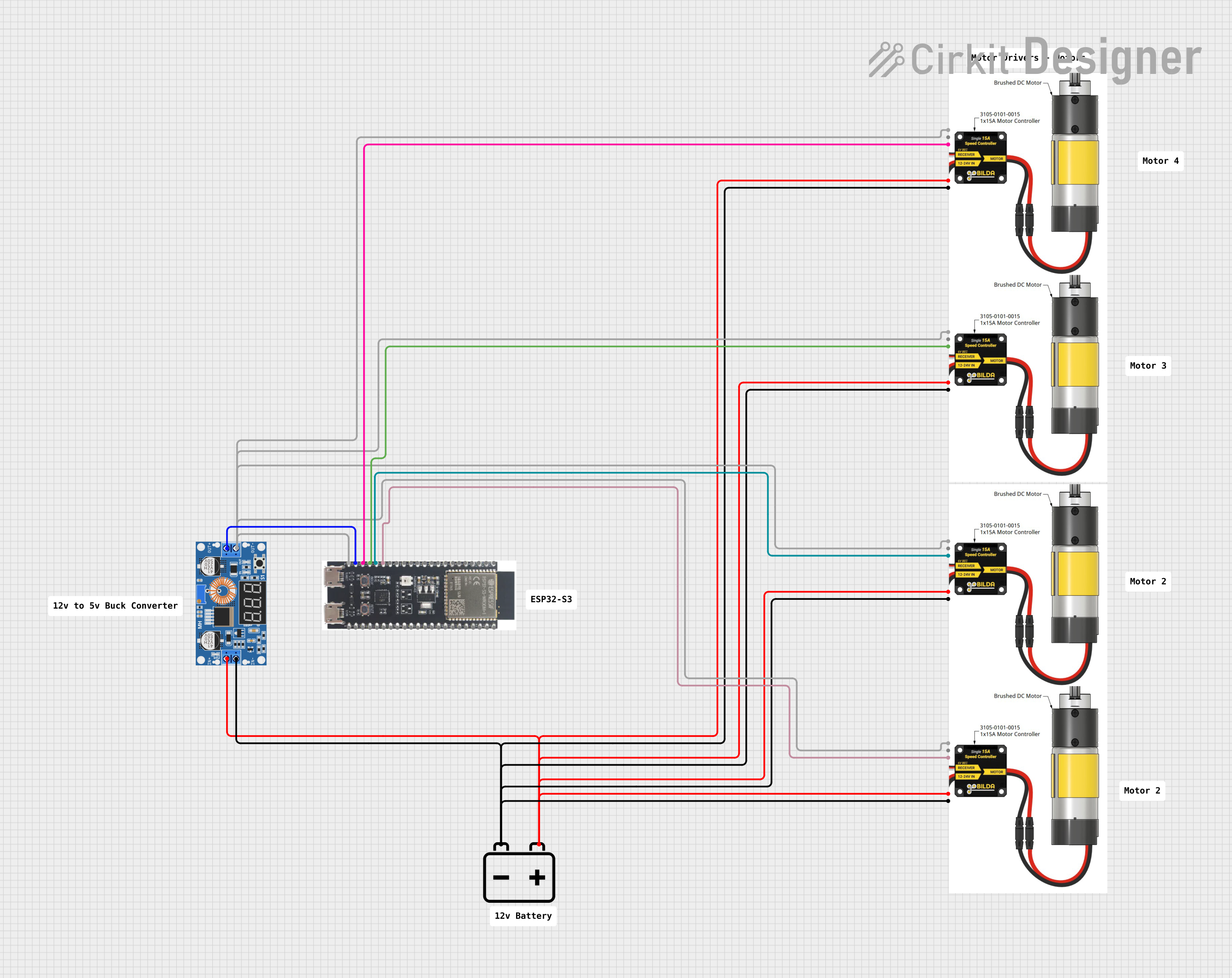 Open Project in Cirkit Designer
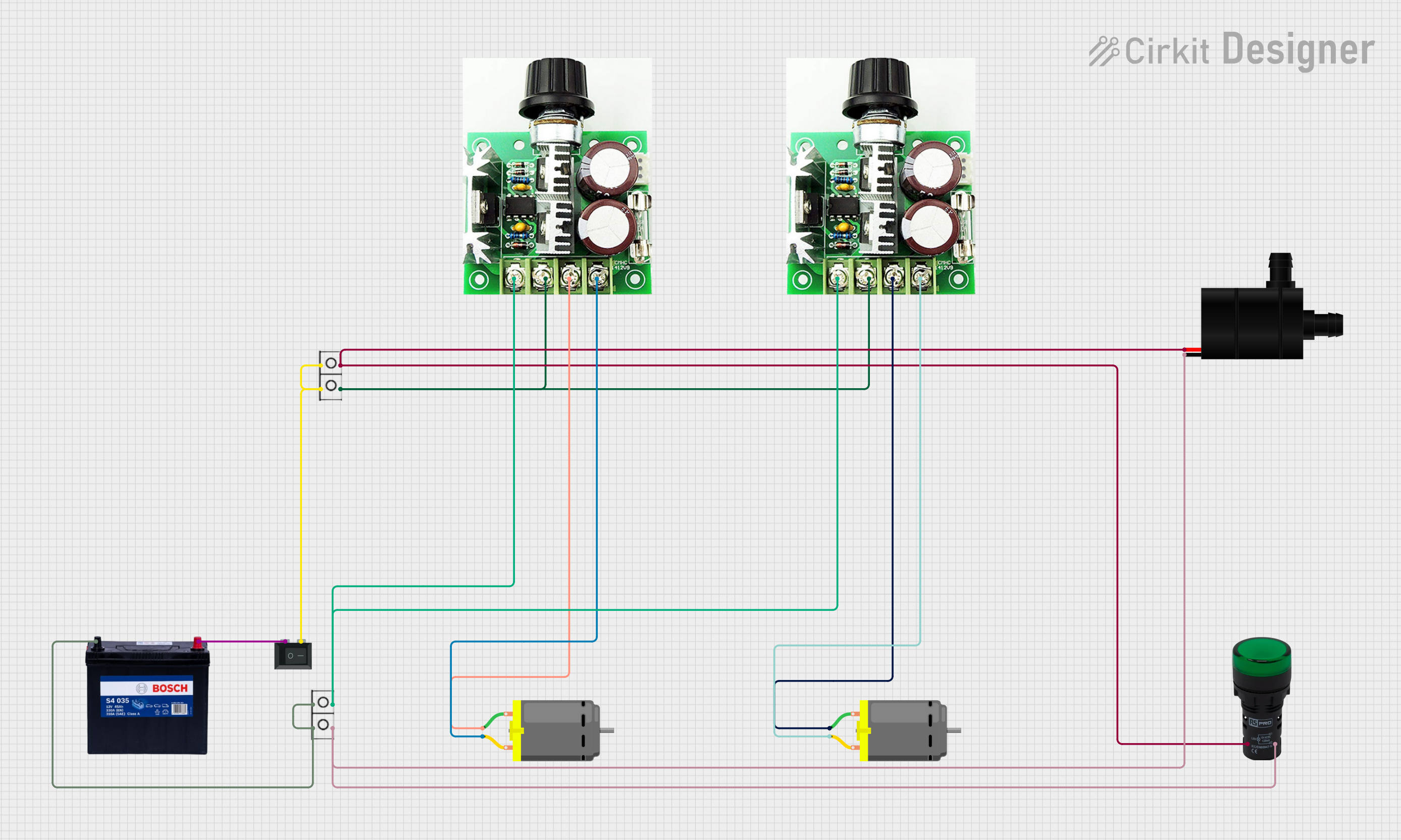 Open Project in Cirkit Designer
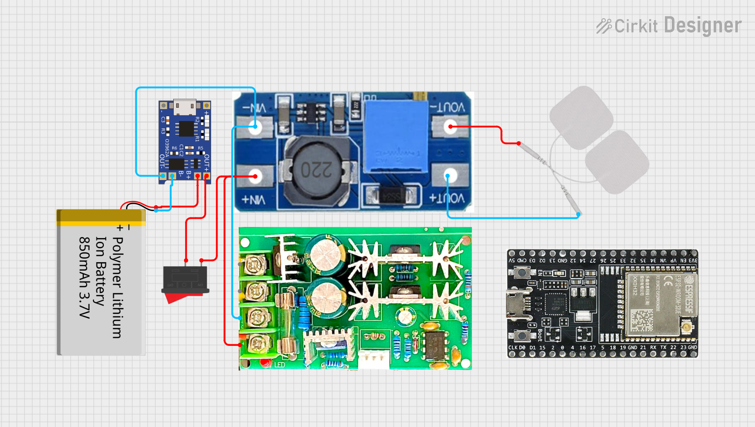 Open Project in Cirkit Designer
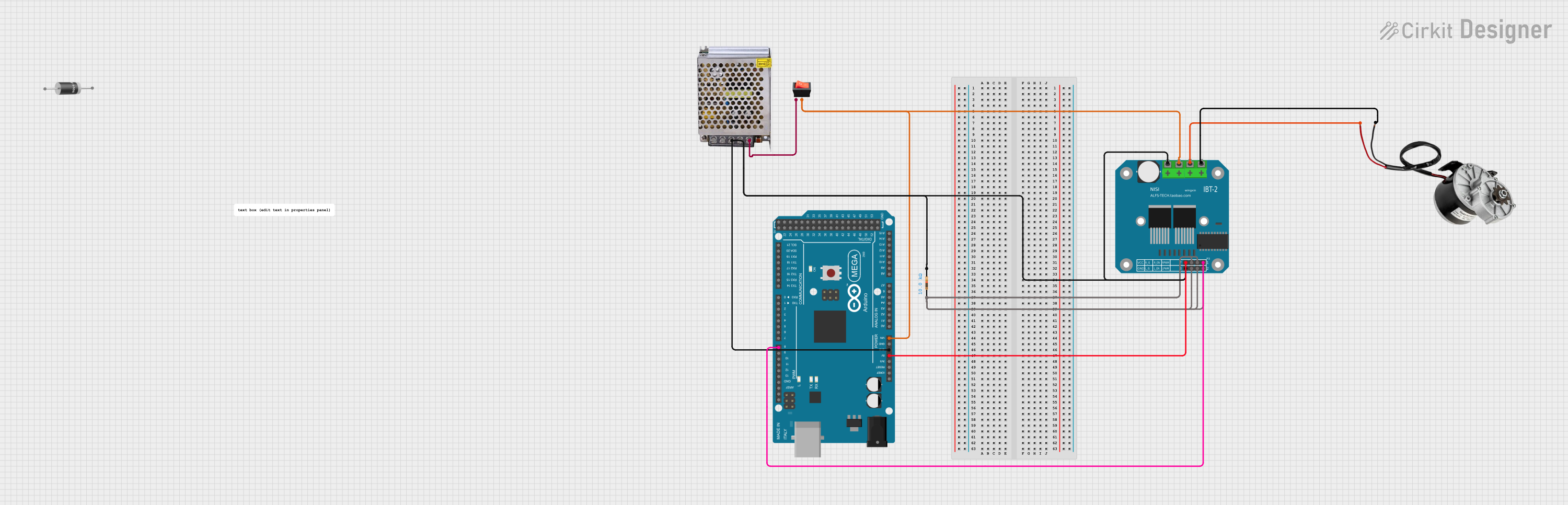 Open Project in Cirkit Designer
Explore Projects Built with SmartElex 15S DC Motor Driver 15A (30A Peak) (Single Motor, PWM)
Open Project in Cirkit DesignerOpen Project in Cirkit DesignerOpen Project in Cirkit DesignerOpen Project in Cirkit DesignerCommon Applications
- Robotics and automation systems
- Electric vehicles and carts
- Conveyor belts and industrial machinery
- Remote-controlled vehicles
- DIY motorized projects
Technical Specifications
Key Technical Details
| Parameter | Value |
|---|---|
| Operating Voltage Range | 6V to 30V |
| Continuous Current | 15A |
| Peak Current | 30A |
| Control Signal Type | PWM (Pulse Width Modulation) |
| PWM Frequency Range | Up to 20 kHz |
| Logic Voltage Range | 3.3V to 5V |
| Motor Channels | Single |
| Dimensions | 60mm x 50mm x 20mm |
| Weight | 50g |
Pin Configuration and Descriptions
| Pin Name | Description |
|---|---|
| VIN | Power input for the motor (6V to 30V). Connect to the motor power supply. |
| GND | Ground connection for the motor power supply. |
| OUT1 | Motor output terminal 1. Connect to one terminal of the DC motor. |
| OUT2 | Motor output terminal 2. Connect to the other terminal of the DC motor. |
| PWM | PWM input signal for speed control. Accepts 3.3V or 5V logic levels. |
| DIR | Direction control input. High or low signal determines motor rotation. |
| EN | Enable pin. High signal enables the motor driver; low signal disables it. |
Usage Instructions
How to Use the Component in a Circuit
- Power Supply: Connect the VIN and GND pins to a suitable power supply (6V to 30V) capable of providing sufficient current for your motor.
- Motor Connection: Connect the DC motor terminals to the OUT1 and OUT2 pins.
- Control Signals:
- Connect the PWM pin to a PWM-capable output pin of your microcontroller (e.g., Arduino).
- Connect the DIR pin to a digital output pin of your microcontroller to control the motor's direction.
- Optionally, connect the EN pin to another digital output pin to enable or disable the motor driver.
- Logic Voltage: Ensure the control signals (PWM, DIR, EN) are within the 3.3V to 5V range.
- Programming: Use your microcontroller to generate PWM signals for speed control and digital signals for direction control.
Important Considerations and Best Practices
- Heat Dissipation: The driver may heat up during operation. Use a heat sink or active cooling for prolonged high-current usage.
- Current Limitation: Ensure the motor's current draw does not exceed the driver's continuous or peak current ratings.
- Power Supply: Use a stable and adequately rated power supply to avoid voltage drops or damage.
- Wiring: Use thick wires for motor and power connections to handle high currents safely.
- PWM Frequency: Set the PWM frequency within the supported range (up to 20 kHz) for optimal performance.
Example Code for Arduino UNO
// Example code to control the SmartElex 15S DC Motor Driver with Arduino UNO

// Define pin connections
const int pwmPin = 9;  // PWM signal pin (connect to PWM pin on motor driver)
const int dirPin = 8;  // Direction control pin (connect to DIR pin on motor driver)
const int enPin = 7;   // Enable pin (connect to EN pin on motor driver)

void setup() {
  // Set pin modes
  pinMode(pwmPin, OUTPUT);
  pinMode(dirPin, OUTPUT);
  pinMode(enPin, OUTPUT);

  // Enable the motor driver
  digitalWrite(enPin, HIGH);
}

void loop() {
  // Rotate motor in one direction at 50% speed
  digitalWrite(dirPin, HIGH);  // Set direction
  analogWrite(pwmPin, 128);    // Set speed (128 = 50% duty cycle)
  delay(2000);                 // Run for 2 seconds

  // Rotate motor in the opposite direction at 75% speed
  digitalWrite(dirPin, LOW);   // Change direction
  analogWrite(pwmPin, 192);    // Set speed (192 = 75% duty cycle)
  delay(2000);                 // Run for 2 seconds
}
Troubleshooting and FAQs
Common Issues and Solutions
Motor Not Running:
- Ensure the EN pin is set to HIGH to enable the motor driver.
- Verify that the power supply voltage is within the specified range (6V to 30V).
- Check all connections, especially the motor and power supply wiring.
Motor Running in the Wrong Direction:
- Check the DIR pin signal. A HIGH or LOW signal determines the motor's rotation direction.
- Swap the motor connections at OUT1 and OUT2 if needed.
Motor Speed Not Changing:
- Ensure the PWM signal is being generated correctly by the microcontroller.
- Verify that the PWM frequency is within the supported range (up to 20 kHz).
Driver Overheating:
- Reduce the motor load or current draw.
- Add a heat sink or active cooling to the motor driver.
No Response from the Driver:
- Check if the control signals (PWM, DIR, EN) are within the 3.3V to 5V logic range.
- Inspect the power supply for stability and sufficient current capacity.
FAQs
Q1: Can I use this driver with a 24V motor?
Yes, the driver supports motors with operating voltages between 6V and 30V, including 24V motors.
Q2: What happens if the motor draws more than 15A?
The driver can handle peak currents of up to 30A for short durations. Prolonged overcurrent may cause overheating or damage.
Q3: Can I control the motor driver with a Raspberry Pi?
Yes, the driver accepts 3.3V logic signals, making it compatible with Raspberry Pi GPIO pins.
Q4: Is reverse polarity protection included?
No, the driver does not have built-in reverse polarity protection. Ensure correct polarity when connecting the power supply.