How to Use DFRobot DFR1071 GP8211S 0-5V/10V 15-bit: Examples, Pinouts, and Specs
Introduction
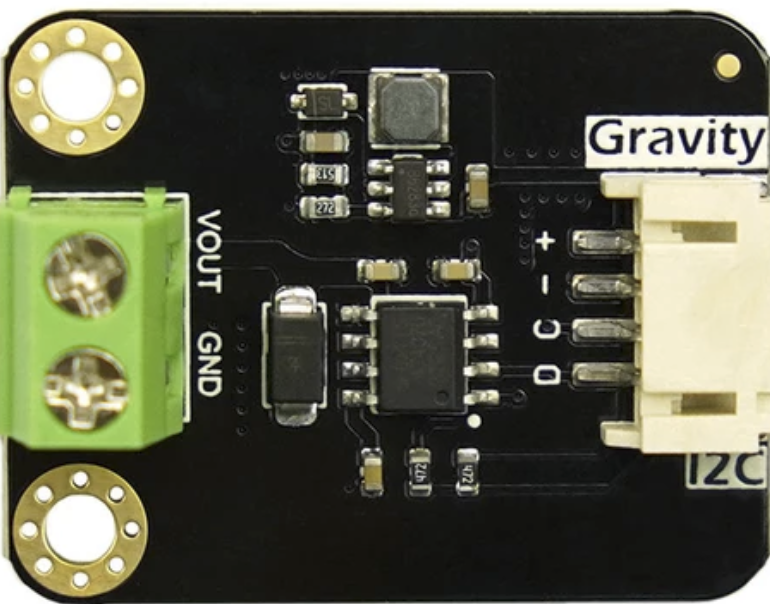
The DFRobot DFR1071 GP8211S is a high-resolution digital-to-analog converter (DAC) designed to provide precise analog signal generation. With a 15-bit resolution, it supports output voltage levels of 0-5V or 0-10V, making it ideal for applications requiring fine control over analog signals. This component is widely used in industrial automation, signal processing, and laboratory instrumentation.
Explore Projects Built with DFRobot DFR1071 GP8211S 0-5V/10V 15-bit

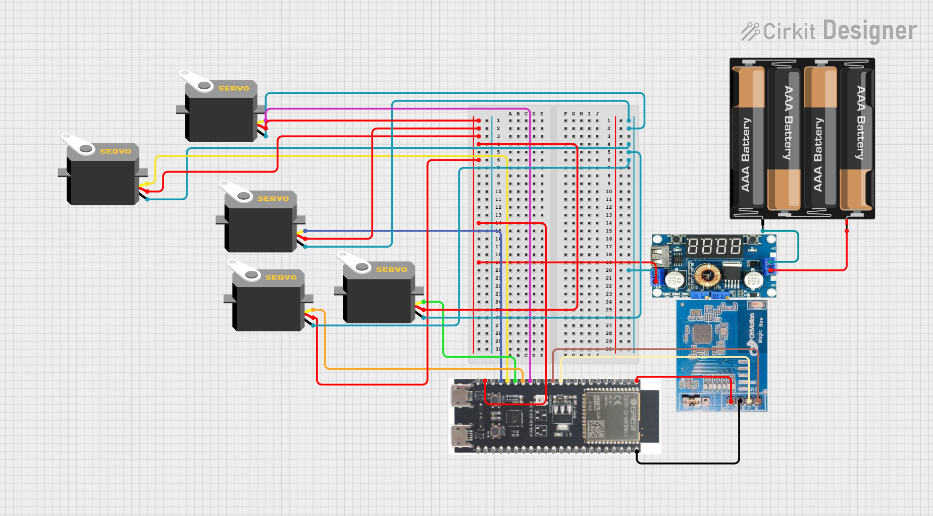
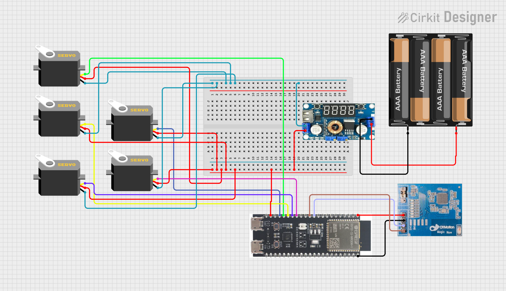

Explore Projects Built with DFRobot DFR1071 GP8211S 0-5V/10V 15-bit
Common Applications and Use Cases
- Industrial control systems
- Signal generation for testing and calibration
- Analog signal interfacing with microcontrollers
- Audio signal processing
- Laboratory instrumentation requiring high precision
Technical Specifications
The following table outlines the key technical details of the DFRobot DFR1071 GP8211S DAC:
| Parameter | Specification |
|---|---|
| Manufacturer | DFRobot |
| Part Number | DFR1071 |
| Resolution | 15-bit |
| Output Voltage Range | 0-5V or 0-10V (selectable) |
| Input Interface | I2C |
| Supply Voltage | 5V |
| Output Current | Up to 10mA |
| Operating Temperature | -40°C to 85°C |
| Dimensions | 30mm x 22mm |
Pin Configuration and Descriptions
The DFR1071 module has the following pinout:
| Pin Name | Description |
|---|---|
| VCC | Power supply input (5V) |
| GND | Ground |
| SDA | I2C data line |
| SCL | I2C clock line |
| OUT | Analog voltage output (0-5V or 0-10V) |
| SEL | Voltage range selection (0-5V or 0-10V) |
Usage Instructions
How to Use the Component in a Circuit
- Power Supply: Connect the VCC pin to a 5V power source and the GND pin to ground.
- I2C Communication: Connect the SDA and SCL pins to the corresponding I2C pins on your microcontroller (e.g., Arduino).
- Voltage Range Selection: Use the SEL pin to select the output voltage range:
- Leave SEL unconnected or set it to LOW for a 0-5V range.
- Set SEL to HIGH for a 0-10V range.
- Analog Output: The OUT pin provides the analog voltage output based on the digital input sent via I2C.
Important Considerations and Best Practices
- Ensure the power supply is stable and within the specified 5V range to avoid damage.
- Use pull-up resistors (typically 4.7kΩ) on the SDA and SCL lines for proper I2C communication.
- Avoid exceeding the maximum output current of 10mA to prevent overloading the DAC.
- For optimal performance, keep the module away from sources of electrical noise.
Example Code for Arduino UNO
Below is an example of how to use the DFR1071 with an Arduino UNO to generate a 2.5V output (assuming a 0-5V range):
#include <Wire.h> // Include the Wire library for I2C communication

#define DAC_I2C_ADDRESS 0x58 // Default I2C address of the DFR1071

void setup() {
  Wire.begin(); // Initialize I2C communication
  Serial.begin(9600); // Initialize serial communication for debugging
  setDACOutput(32768); // Set DAC output to mid-scale (2.5V for 0-5V range)
}

void loop() {
  // The DAC output remains constant unless updated
}

// Function to set the DAC output
void setDACOutput(uint16_t value) {
  // Ensure the value is within the 15-bit range (0 to 32767)
  if (value > 32767) value = 32767;

  Wire.beginTransmission(DAC_I2C_ADDRESS); // Start I2C communication
  Wire.write((value >> 8) & 0xFF); // Send the high byte of the 15-bit value
  Wire.write(value & 0xFF); // Send the low byte of the 15-bit value
  Wire.endTransmission(); // End I2C communication

  Serial.print("DAC Output Set to: ");
  Serial.println(value);
}
Notes on the Code
- The
setDACOutputfunction takes a 15-bit value (0 to 32767) and sends it to the DAC via I2C. - For a 0-5V range, a value of 0 corresponds to 0V, and 32767 corresponds to 5V.
- Adjust the value based on the desired output voltage.
Troubleshooting and FAQs
Common Issues and Solutions
No Output Voltage
- Ensure the power supply is connected and providing 5V.
- Verify the I2C connections (SDA and SCL) and check for proper pull-up resistors.
- Confirm the SEL pin is set correctly for the desired voltage range.
Incorrect Output Voltage
- Check the digital input value sent to the DAC and ensure it is within the 15-bit range.
- Verify the SEL pin configuration matches the intended voltage range (0-5V or 0-10V).
I2C Communication Failure
- Ensure the I2C address (default: 0x58) matches the one used in your code.
- Check for loose or incorrect wiring on the SDA and SCL lines.
- Use an I2C scanner sketch to confirm the DAC is detected on the bus.
FAQs
Q: Can I use the DFR1071 with a 3.3V microcontroller?
A: Yes, but you must use level shifters for the I2C lines to ensure compatibility with the 5V logic of the DAC.
Q: How do I change the I2C address of the DAC?
A: The DFR1071 has a fixed I2C address (0x58) and does not support address modification.
Q: What happens if I exceed the maximum output current?
A: Exceeding the 10mA limit may damage the DAC or cause incorrect output behavior. Always use a buffer circuit if higher current is required.
Q: Can I use the DAC for audio applications?
A: Yes, the high resolution and precision make it suitable for audio signal generation, but ensure the output is properly filtered for smooth waveforms.