How to Use ESP32-C6 : Examples, Pinouts, and Specs
Introduction
The ESP32-C6 is a low-power, dual-core microcontroller developed by Sparkfun under the part ID Qwiic. It is designed for Internet of Things (IoT) applications, offering integrated Wi-Fi 6 and Bluetooth 5 (LE) capabilities. Built on a 32-bit RISC-V architecture, the ESP32-C6 is highly versatile, supporting a wide range of peripherals and communication protocols. Its low power consumption and robust connectivity make it ideal for smart devices, home automation, wearables, and industrial IoT systems.
Explore Projects Built with ESP32-C6


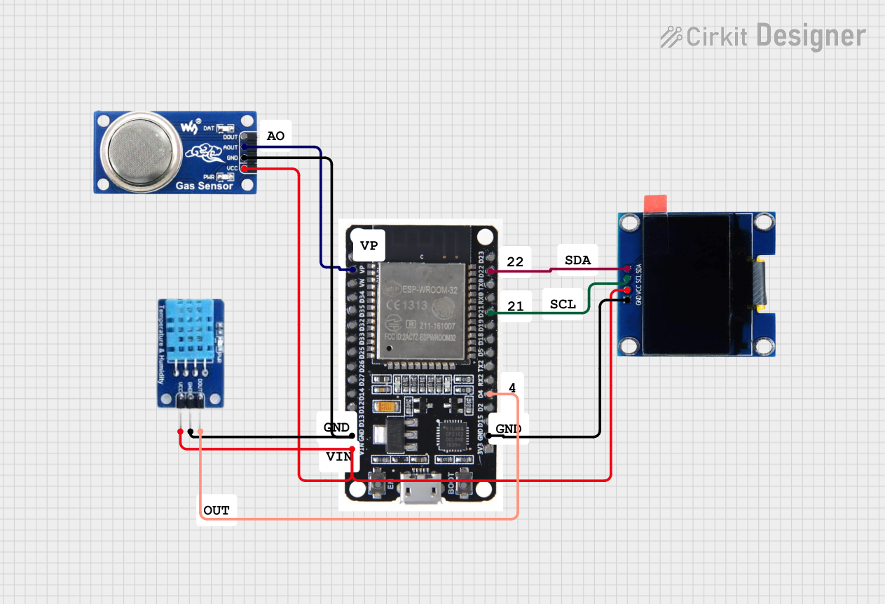
Explore Projects Built with ESP32-C6
Common Applications
- Smart home devices (e.g., smart lights, thermostats)
- Wearable technology
- Industrial IoT systems
- Wireless sensor networks
- Low-power Bluetooth applications
- Edge computing and AI/ML at the edge
Technical Specifications
Key Technical Details
| Parameter | Value |
|---|---|
| Architecture | 32-bit RISC-V |
| Clock Speed | Up to 160 MHz |
| Flash Memory | 4 MB (external flash supported) |
| RAM | 512 KB SRAM |
| Wi-Fi Standard | Wi-Fi 6 (802.11ax) |
| Bluetooth | Bluetooth 5 (LE) |
| GPIO Pins | 22 (multiplexed with other functions) |
| Operating Voltage | 3.3V |
| Power Consumption | Ultra-low power modes available (deep sleep current < 10 µA) |
| Communication Interfaces | UART, SPI, I2C, I2S, PWM, ADC, DAC |
| ADC Resolution | 12-bit |
| Operating Temperature Range | -40°C to +85°C |
| Package | QFN48 |
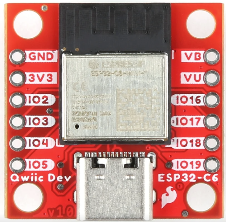
Pin Configuration and Descriptions
The ESP32-C6 has a total of 48 pins, with 22 GPIOs that can be configured for various functions. Below is a summary of the key pins:
| Pin Name | Type | Description |
|---|---|---|
| GPIO0 | Input/Output | General-purpose I/O, can also be used for boot mode selection. |
| GPIO1 | Input/Output | General-purpose I/O, UART TX by default. |
| GPIO2 | Input/Output | General-purpose I/O, supports ADC and PWM. |
| GPIO3 | Input/Output | General-purpose I/O, UART RX by default. |
| GPIO4 | Input/Output | General-purpose I/O, supports ADC and PWM. |
| GPIO5 | Input/Output | General-purpose I/O, supports ADC and PWM. |
| GND | Power | Ground connection. |
| 3V3 | Power | 3.3V power supply input. |
| EN | Input | Enable pin. Pull high to enable the chip. |
| ADC1_CH0 | Analog Input | ADC channel 0, supports 12-bit resolution. |
| ADC1_CH1 | Analog Input | ADC channel 1, supports 12-bit resolution. |
| DAC1 | Analog Output | Digital-to-analog converter output channel 1. |
| DAC2 | Analog Output | Digital-to-analog converter output channel 2. |
Usage Instructions
How to Use the ESP32-C6 in a Circuit
- Power Supply: Provide a stable 3.3V power supply to the 3V3 pin. Ensure the ground (GND) is connected to the circuit's common ground.
- Boot Mode: To upload code, connect GPIO0 to GND during reset to enter bootloader mode.
- Programming: Use the Sparkfun Qwiic interface or a USB-to-serial adapter to program the ESP32-C6. The chip is compatible with the Arduino IDE and ESP-IDF.
- Peripherals: Connect peripherals (e.g., sensors, actuators) to the GPIO pins. Configure the pins in your code for the desired function (e.g., input, output, ADC, PWM).
Important Considerations
- Voltage Levels: Ensure all connected peripherals operate at 3.3V logic levels. Use level shifters if interfacing with 5V devices.
- Power Consumption: Use deep sleep modes to minimize power consumption in battery-powered applications.
- Antenna Placement: For optimal Wi-Fi and Bluetooth performance, ensure the onboard antenna is not obstructed by metal or other conductive materials.
Example Code for Arduino UNO
Below is an example of using the ESP32-C6 to read an analog sensor and send data over Wi-Fi:
#include <WiFi.h> // Include the Wi-Fi library

// Wi-Fi credentials
const char* ssid = "Your_SSID";
const char* password = "Your_PASSWORD";

// Analog pin for sensor input
const int sensorPin = 34; // GPIO34 (ADC1_CH0)

void setup() {
  Serial.begin(115200); // Initialize serial communication
  WiFi.begin(ssid, password); // Connect to Wi-Fi

  // Wait for Wi-Fi connection
  while (WiFi.status() != WL_CONNECTED) {
    delay(500);
    Serial.print(".");
  }
  Serial.println("\nWi-Fi connected!");
}

void loop() {
  int sensorValue = analogRead(sensorPin); // Read analog value from sensor
  float voltage = sensorValue * (3.3 / 4095.0); // Convert to voltage

  // Print sensor value and voltage
  Serial.print("Sensor Value: ");
  Serial.print(sensorValue);
  Serial.print(" | Voltage: ");
  Serial.println(voltage);

  delay(1000); // Wait 1 second before next reading
}
Troubleshooting and FAQs
Common Issues and Solutions
ESP32-C6 Not Connecting to Wi-Fi
- Solution: Double-check the SSID and password in your code. Ensure the router is within range and supports 2.4 GHz Wi-Fi (ESP32-C6 does not support 5 GHz Wi-Fi).
Code Upload Fails
- Solution: Ensure GPIO0 is connected to GND during reset to enter bootloader mode. Verify the correct COM port and board settings in the Arduino IDE.
Unstable Power Supply
- Solution: Use a decoupling capacitor (e.g., 10 µF) near the 3V3 pin to stabilize the power supply.
Low Wi-Fi Signal Strength
- Solution: Check the placement of the ESP32-C6 module. Avoid placing it near metal objects or inside enclosures that block RF signals.
FAQs
Q: Can the ESP32-C6 operate on 5V?
A: No, the ESP32-C6 operates at 3.3V. Use a voltage regulator or level shifter for 5V systems.Q: Does the ESP32-C6 support OTA updates?
A: Yes, the ESP32-C6 supports Over-The-Air (OTA) firmware updates.Q: Can I use the ESP32-C6 with the Arduino IDE?
A: Yes, the ESP32-C6 is fully compatible with the Arduino IDE. Install the ESP32 board package to get started.Q: What is the maximum range of Wi-Fi and Bluetooth?
A: Wi-Fi range is approximately 30 meters indoors and 100 meters outdoors. Bluetooth range depends on the environment but typically reaches up to 50 meters.
This documentation provides a comprehensive guide to the Sparkfun ESP32-C6 (Qwiic), ensuring users can effectively integrate it into their projects.