How to Use lcd module 16*2: Examples, Pinouts, and Specs
Introduction
The 16x2 LCD module is a popular electronic display interface that can show 16 characters per line over 2 lines, providing a simple way to present text data. This module is widely used in various electronic projects and devices, such as calculators, microwave ovens, and DIY Arduino projects, due to its ease of use and low power consumption.
Explore Projects Built with lcd module 16*2
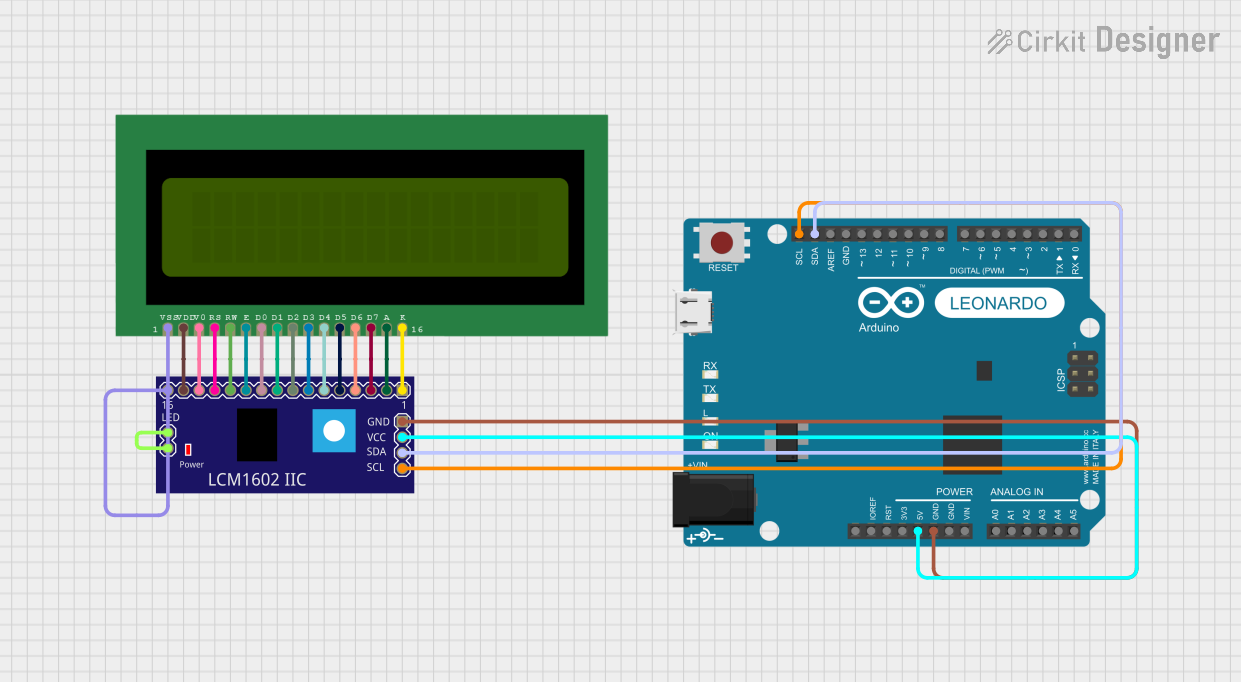

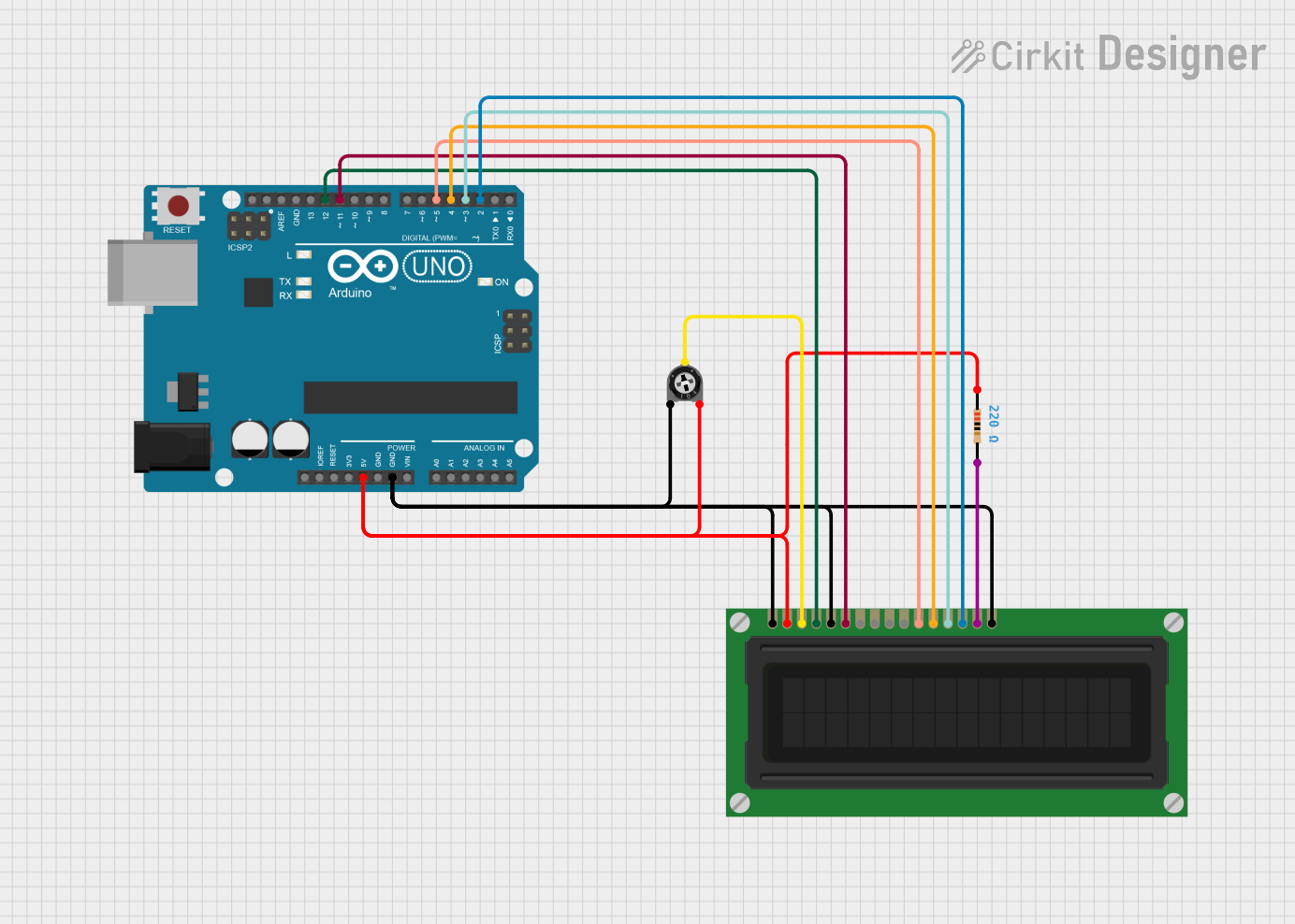
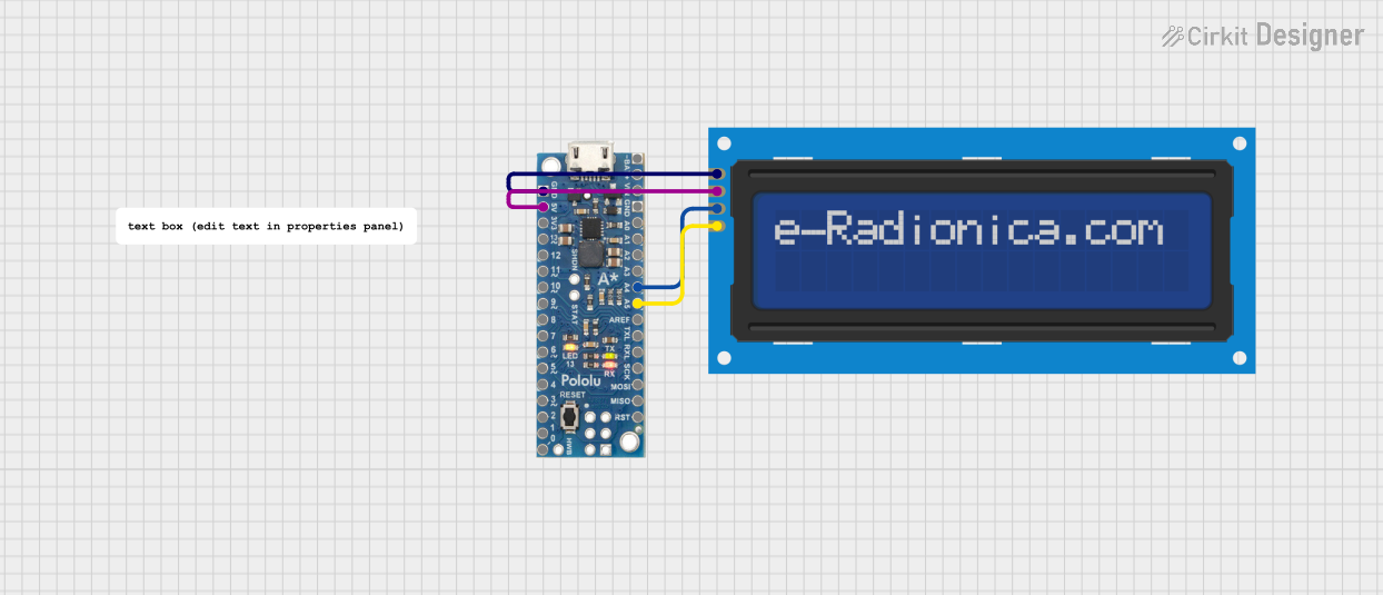
Explore Projects Built with lcd module 16*2
Technical Specifications
Key Technical Details
- Display Type: Alphanumeric LCD
- Display Mode: STN, Positive, Transflective
- Resolution: 16 characters x 2 lines
- Character Size: 5x8 or 5x10 dot matrix
- Backlight: LED, Yellow-Green or Blue
- Operating Voltage: Typically 4.7V to 5.3V
- Module Dimensions: 80mm x 36mm x 12mm (approx.)
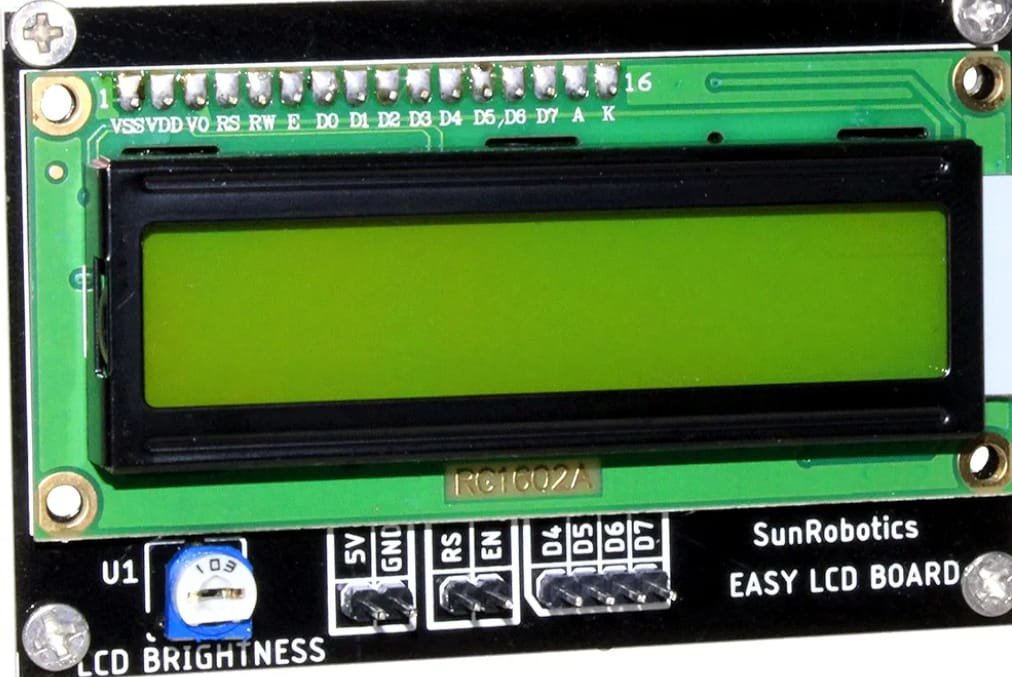
Pin Configuration and Descriptions
| Pin No. | Symbol | Function |
|---|---|---|
| 1 | VSS | Ground |
| 2 | VDD | Power supply (4.7V to 5.3V) |
| 3 | V0 | Contrast adjustment |
| 4 | RS | Register Select: 0 for instruction input, 1 for data input |
| 5 | R/W | Read/Write: 0 for write, 1 for read |
| 6 | E | Enable signal |
| 7-14 | D0-D7 | Data bus lines |
| 15 | A | Anode for backlight (+) |
| 16 | K | Cathode for backlight (-) |
Usage Instructions
Connecting to a Circuit
- Power Connections: Connect pin 1 to ground and pin 2 to a 5V supply.
- Contrast Adjustment: Connect pin 3 to a potentiometer for contrast control.
- Data Interface: For a 4-bit interface, connect pins 7-10 to ground and pins 11-14 to the microcontroller data pins. For an 8-bit interface, connect all data pins (D0-D7) to the microcontroller.
- Control Pins: Connect RS and E to two digital pins on the microcontroller. Optionally, connect R/W to ground if only writing to the display.
- Backlight: Connect pin 15 to 5V through a current-limiting resistor and pin 16 to ground.
Programming with Arduino
#include <LiquidCrystal.h>

// Initialize the library with the numbers of the interface pins
LiquidCrystal lcd(12, 11, 5, 4, 3, 2);

void setup() {
  // Set up the LCD's number of columns and rows:
  lcd.begin(16, 2);
  // Print a message to the LCD.
  lcd.print("Hello, World!");
}

void loop() {
  // Set the cursor to column 0, line 1
  // (note: line 1 is the second row, since counting begins with 0):
  lcd.setCursor(0, 1);
  // Print the number of seconds since reset:
  lcd.print(millis() / 1000);
}
Important Considerations and Best Practices
- Always use a current-limiting resistor for the backlight to prevent damage.
- Adjust the contrast potentiometer to ensure characters are visible.
- Use a 4-bit interface to save microcontroller pins if needed.
- Ensure the power supply is stable to avoid erratic display behavior.
Troubleshooting and FAQs
Common Issues
- Display is blank or characters are not visible: Adjust the contrast potentiometer.
- Garbled characters on the display: Check the data connections and ensure proper initialization in the code.
- Backlight not working: Verify the connections to pins 15 and 16 and the current-limiting resistor.
Solutions and Tips
- If the display is not initializing properly, insert a small delay after powering up before sending commands.
- Use the
lcd.clear()function to clear the display before printing new text. - Ensure that the
lcd.begin(16, 2)function matches the display's configuration.
FAQs
Q: Can I use the 16x2 LCD module with a 3.3V system? A: It is designed for 5V operation, but some modules may work at 3.3V with reduced contrast. Check the datasheet for your specific module.
Q: How do I control the backlight brightness? A: Use a PWM signal to the backlight anode or adjust the current-limiting resistor value.
Q: What is the maximum length of the data cables? A: Keep the data cables as short as possible to prevent signal degradation, ideally less than 30 cm.
Q: Can I display custom characters? A: Yes, the 16x2 LCD module supports custom character creation using its CGRAM (Character Generator RAM).
This documentation provides a comprehensive guide to using the 16x2 LCD module with an Arduino UNO or similar microcontroller. For further details, consult the datasheet of the specific LCD module you are using.