How to Use usb c male : Examples, Pinouts, and Specs
Introduction
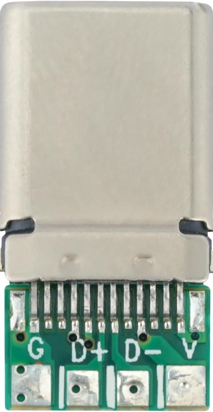
The USB Type-C male connector is a versatile and compact interface designed for data transfer and power delivery. Its reversible design eliminates the frustration of incorrect orientation during connection, making it user-friendly and efficient. This connector supports high-speed data transfer, video output, and power delivery, making it a popular choice for modern electronic devices such as smartphones, laptops, and peripherals.
Explore Projects Built with usb c male


Explore Projects Built with usb c male
Common Applications and Use Cases
- Charging and powering devices (e.g., smartphones, laptops, tablets)
- High-speed data transfer between devices
- Video output for monitors and displays (e.g., USB-C to HDMI)
- Peripheral connections (e.g., external hard drives, docking stations)
- Embedded systems and DIY electronics projects
Technical Specifications
The USB Type-C male connector adheres to the USB 3.1/3.2 or USB4 standards, depending on the specific implementation. Below are the general technical specifications:
| Parameter | Specification |
|---|---|
| Connector Type | USB Type-C Male |
| Data Transfer Rate | Up to 40 Gbps (USB4), 10 Gbps (USB 3.1 Gen 2) |
| Power Delivery (PD) | Up to 100W (20V, 5A) |
| Reversible Design | Yes |
| Number of Pins | 24 |
| Operating Temperature | -40°C to 85°C |
| Durability | 10,000+ insertion/removal cycles |
Pin Configuration and Descriptions
The USB Type-C male connector has 24 pins, symmetrically arranged to support its reversible design. Below is the pinout and description:
| Pin Number | Name | Description |
|---|---|---|
| A1, B1 | GND | Ground |
| A2, B2 | TX1+ | SuperSpeed differential pair (positive) |
| A3, B3 | TX1- | SuperSpeed differential pair (negative) |
| A4, B4 | VBUS | Power supply (up to 20V, 5A) |
| A5, B5 | CC1, CC2 | Configuration channel for power delivery and role |
| A6, B6 | D+ | USB 2.0 differential pair (positive) |
| A7, B7 | D- | USB 2.0 differential pair (negative) |
| A8, B8 | SBU1, SBU2 | Sideband use (e.g., audio, alternate modes) |
| A9, B9 | RX2- | SuperSpeed differential pair (negative) |
| A10, B10 | RX2+ | SuperSpeed differential pair (positive) |
| A11, B11 | GND | Ground |
| A12, B12 | Shield | Connector shield |
Usage Instructions
How to Use the USB Type-C Male Connector in a Circuit
- Soldering the Connector:
- Use a PCB with a USB Type-C footprint to solder the connector securely.
- Ensure proper alignment of the pins to avoid short circuits.
- Power Delivery:
- Connect the VBUS and GND pins to the power source.
- Use the CC1 and CC2 pins to negotiate power delivery roles (e.g., source or sink).
- Data Transfer:
- Connect the TX/RX differential pairs for high-speed data transfer.
- Use the D+/D- pins for USB 2.0 communication.
- Alternate Modes:
- Utilize the SBU pins for alternate modes like DisplayPort or audio.
Important Considerations and Best Practices
- Voltage and Current Ratings: Ensure the power source does not exceed the connector's rated voltage (20V) and current (5A).
- Reversible Design: The symmetrical pinout allows the connector to function regardless of orientation.
- Signal Integrity: Use proper PCB trace design and impedance matching for high-speed signals.
- Heat Dissipation: For high-power applications, ensure adequate heat dissipation to prevent overheating.
Example: Connecting USB Type-C to Arduino UNO
While the Arduino UNO does not natively support USB Type-C, you can use a USB Type-C breakout board to interface with it. Below is an example of using the USB Type-C connector for power delivery:
// Example: Using USB Type-C to power an Arduino UNO
// Connect the VBUS pin of the USB Type-C breakout board to the Arduino's VIN pin.
// Connect the GND pin of the USB Type-C breakout board to the Arduino's GND pin.

void setup() {
  // Initialize the onboard LED pin as an output
  pinMode(LED_BUILTIN, OUTPUT);
}

void loop() {
  // Blink the onboard LED to confirm power delivery
  digitalWrite(LED_BUILTIN, HIGH); // Turn the LED on
  delay(1000);                     // Wait for 1 second
  digitalWrite(LED_BUILTIN, LOW);  // Turn the LED off
  delay(1000);                     // Wait for 1 second
}
Troubleshooting and FAQs
Common Issues
- Connector Not Detected:
- Cause: Incorrect pin connections or damaged connector.
- Solution: Verify the pin connections and inspect the connector for physical damage.
- Overheating:
- Cause: Exceeding the rated current or poor heat dissipation.
- Solution: Ensure the current does not exceed 5A and improve ventilation.
- Data Transfer Issues:
- Cause: Signal integrity problems or incorrect wiring.
- Solution: Use high-quality cables and ensure proper PCB trace design.
FAQs
- Can the USB Type-C male connector be used for video output?
- Yes, it supports alternate modes like DisplayPort for video output, but additional circuitry is required.
- Is the USB Type-C male connector backward compatible with USB 2.0?
- Yes, it includes D+/D- pins for USB 2.0 communication.
- How durable is the USB Type-C male connector?
- It is rated for over 10,000 insertion/removal cycles, making it highly durable.
By following this documentation, you can effectively integrate the USB Type-C male connector into your projects for reliable power delivery and data transfer.