How to Use Electric Lock: Examples, Pinouts, and Specs
Introduction
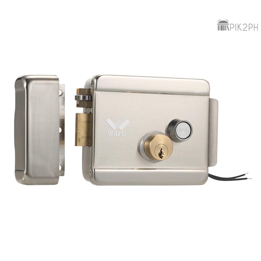
An electric lock is an electromechanical device designed to secure doors, gates, or other entry points by using an electrical current to control the locking mechanism. These locks are widely used in access control systems for residential, commercial, and industrial applications, offering enhanced security and convenience over traditional mechanical locks. Common applications include keyless entry systems, security checkpoints, and automated entry systems in smart homes and buildings.
Explore Projects Built with Electric Lock
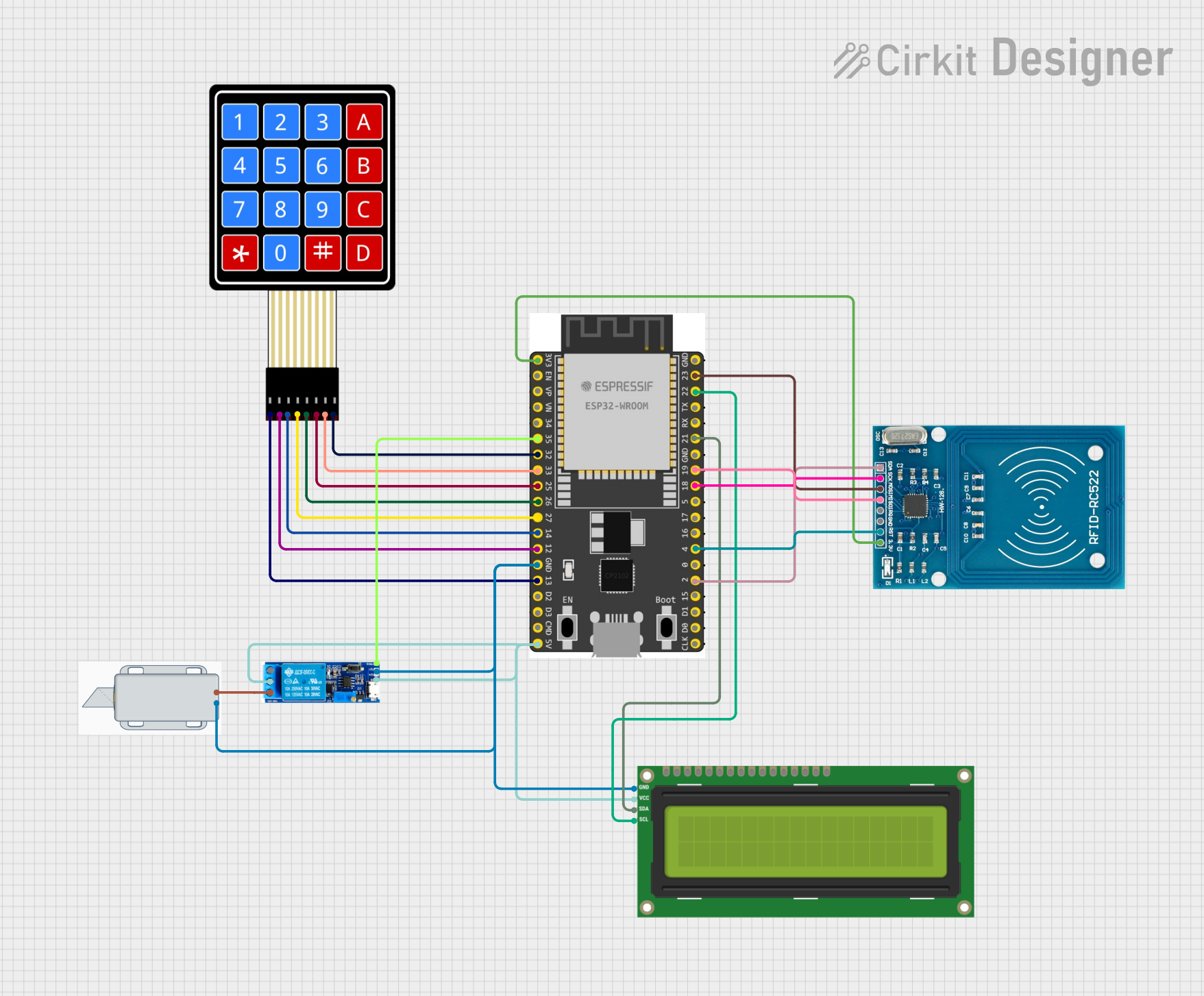
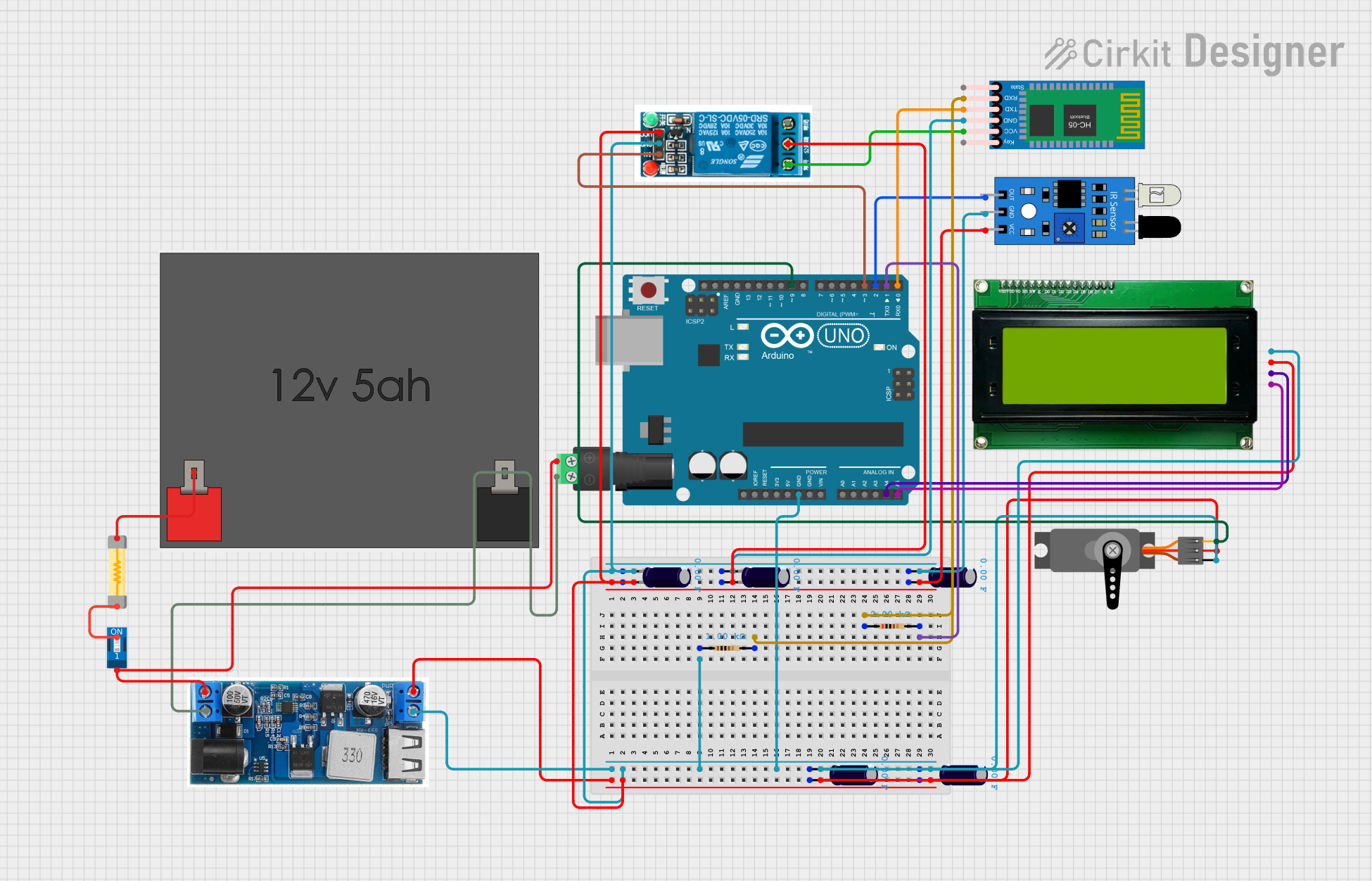
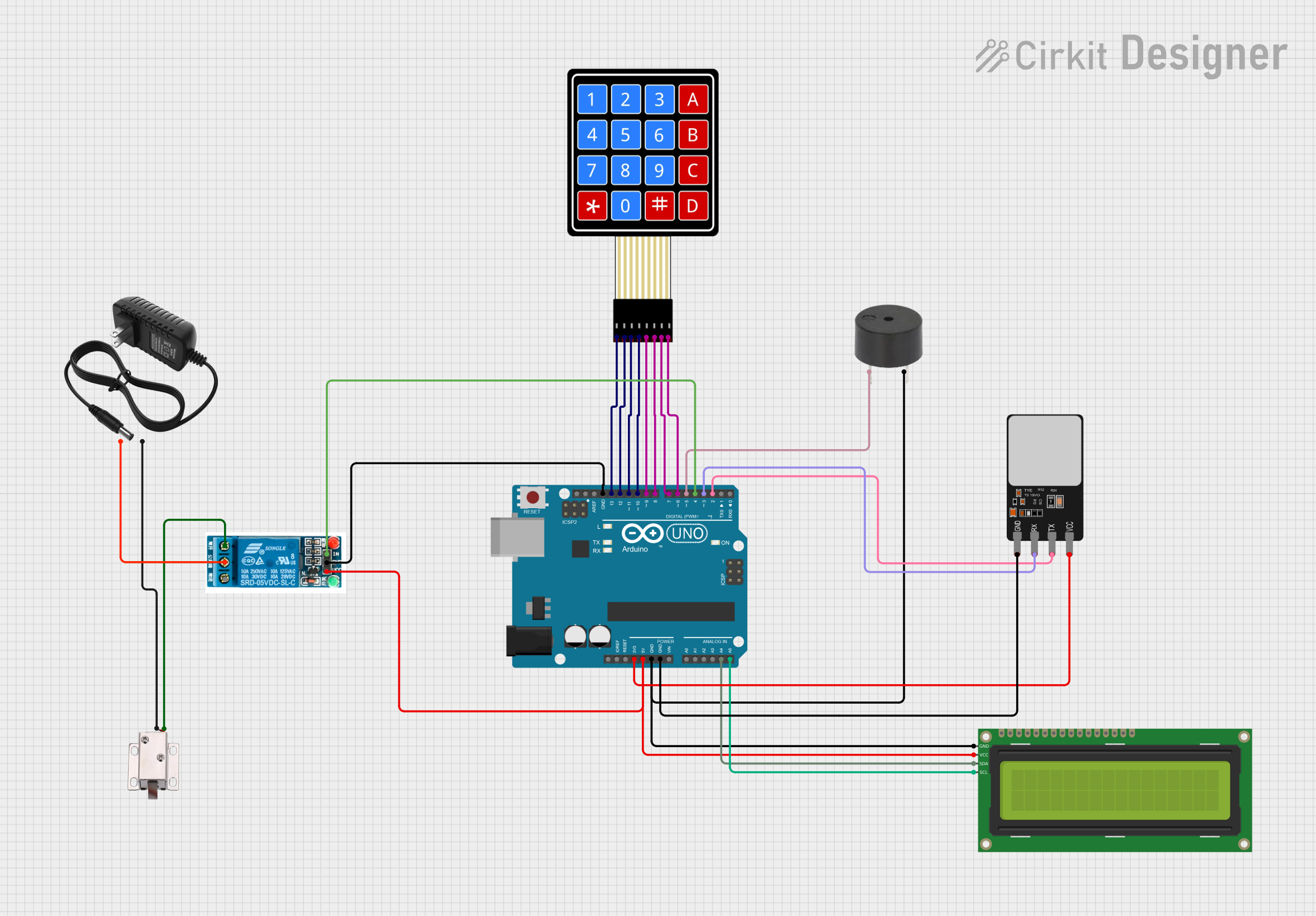

Explore Projects Built with Electric Lock
Technical Specifications
General Specifications
- Operating Voltage: Typically 12V or 24V DC
- Current Draw: Varies with model (e.g., 500mA at 12V DC)
- Holding Force: Ranges from 250kg to 1000kg (550lbs to 2200lbs)
- Operating Temperature: -10°C to +55°C (14°F to 131°F)
- Humidity: 0 to 95% non-condensing
Pin Configuration and Descriptions
| Pin Number | Description | Notes |
|---|---|---|
| 1 | Power (+) | Connect to positive voltage |
| 2 | Power (-) | Connect to ground |
| 3 | Control Input | Trigger for lock actuation |
| 4 | Normally Closed (NC) | Closed when lock is powered |
| 5 | Common (COM) | Common terminal for switches |
| 6 | Normally Open (NO) | Open when lock is powered |
Usage Instructions
Wiring the Electric Lock
- Connect the positive voltage supply to the Power (+) pin.
- Connect the ground to the Power (-) pin.
- The Control Input pin can be connected to a switch, relay, or an output from a microcontroller to actuate the lock.
- The NC and NO pins are used for status indication or to interface with an alarm or monitoring system.
Best Practices
- Ensure the power supply matches the voltage rating of the electric lock.
- Use a diode (e.g., 1N4007) across the lock coil to suppress voltage spikes.
- For safety, always install the lock with a mechanical override option.
- Regularly inspect and maintain the lock for reliable operation.
Troubleshooting and FAQs
Common Issues
- Lock does not engage: Check the power supply voltage and connections.
- Intermittent operation: Inspect wiring for loose connections or damage.
- Lock overheats: Ensure the current draw is within specifications.
FAQs
Q: Can the electric lock be used outdoors? A: Yes, but ensure it is rated for outdoor use and properly sealed against the elements.
Q: How can I test if the lock is working? A: Apply the rated voltage to the Power (+) and (-) pins and use a multimeter to check continuity across the NC or NO pins.
Q: What happens if the power fails? A: Most electric locks are fail-secure, meaning they remain locked if power is lost. Fail-safe models unlock when power is lost.
Example Arduino Code
// Example code to control an Electric Lock with an Arduino UNO

const int lockControlPin = 3; // Connect to Control Input of Electric Lock

void setup() {
  pinMode(lockControlPin, OUTPUT); // Set lock control pin as an output
  digitalWrite(lockControlPin, LOW); // Start with the lock disengaged
}

void loop() {
  // Engage the lock for 5 seconds
  digitalWrite(lockControlPin, HIGH); // Apply voltage to engage lock
  delay(5000); // Wait for 5 seconds

  // Disengage the lock
  digitalWrite(lockControlPin, LOW); // Remove voltage to disengage lock
  delay(5000); // Wait for 5 seconds before next cycle
}
Note: The above code assumes the electric lock is activated by applying a HIGH signal. Some locks may require a LOW signal to engage; adjust the code accordingly. Always include a current-limiting resistor if the control input is not designed for direct connection to a microcontroller.