How to Use Freenove Breakout Board: Examples, Pinouts, and Specs
Introduction
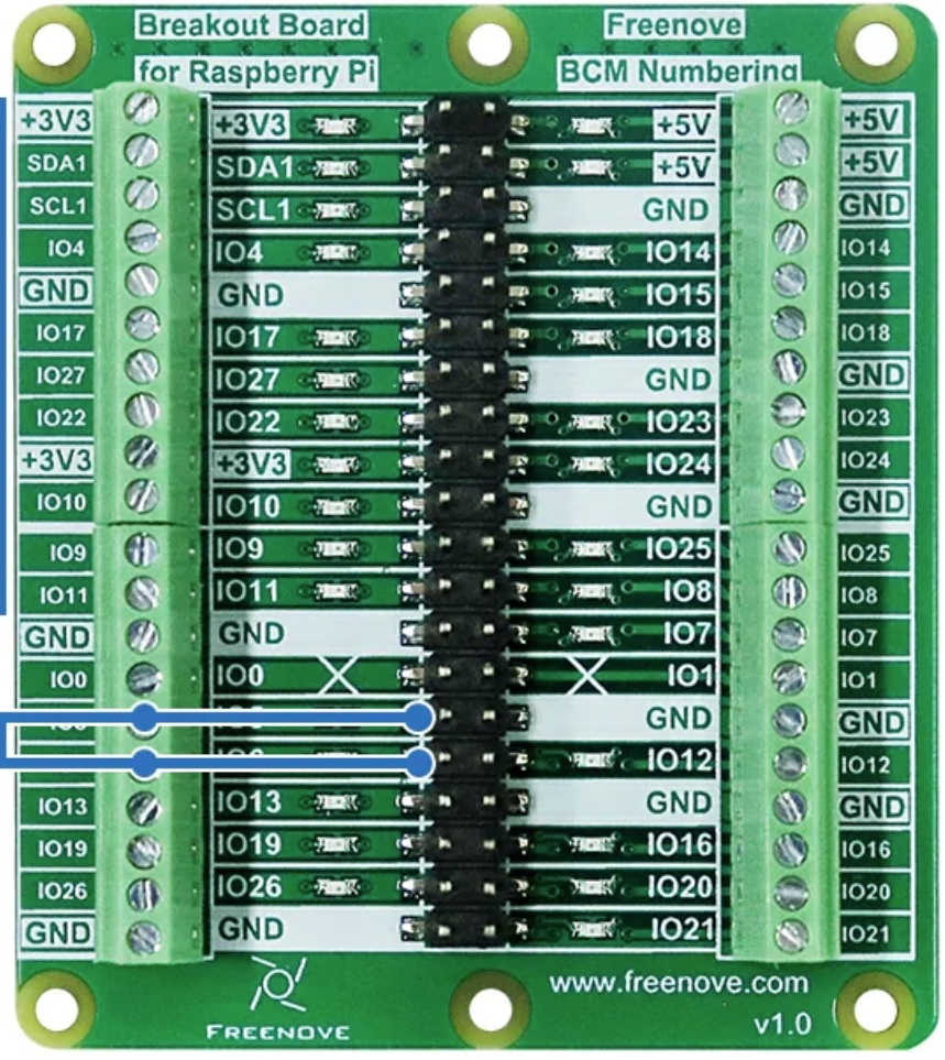
The Freenove Breakout Board (Part ID: FNK0080) is a versatile prototyping board designed to simplify the connection of various electronic components. It features multiple GPIO pins, power supply options, and is compatible with popular microcontrollers such as Arduino, Raspberry Pi, and ESP32. This breakout board is ideal for hobbyists, students, and professionals working on electronics projects, as it provides a convenient platform for rapid prototyping and testing.
Explore Projects Built with Freenove Breakout Board
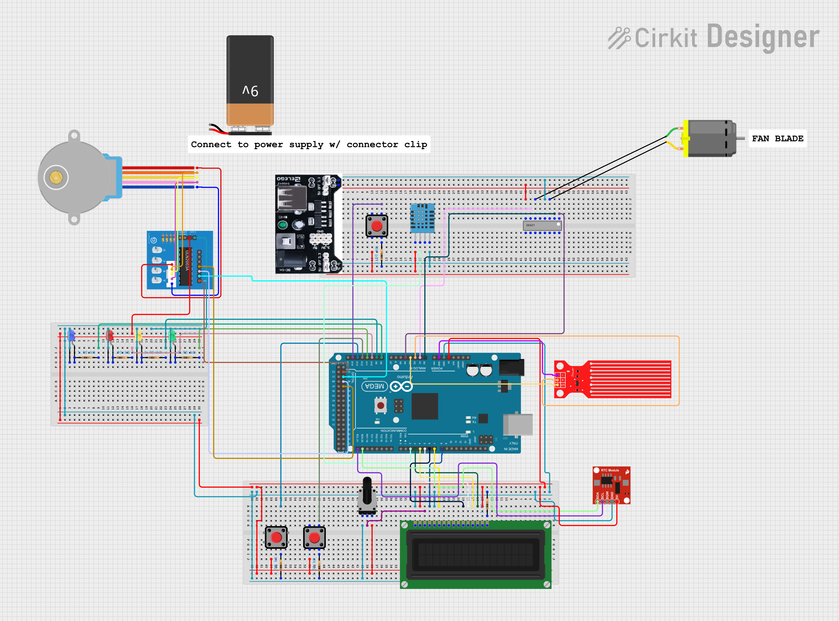
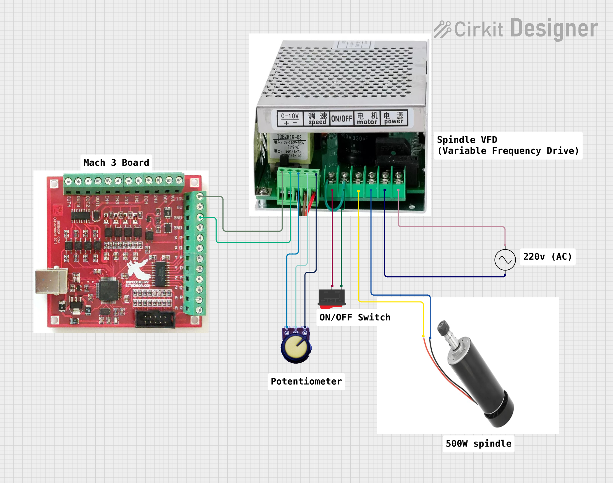
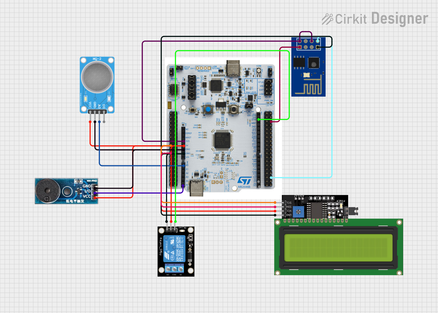
Explore Projects Built with Freenove Breakout Board
Common Applications and Use Cases
- Prototyping circuits for Arduino, Raspberry Pi, or ESP32 projects.
- Connecting sensors, actuators, and other peripherals.
- Educational purposes for learning electronics and programming.
- Rapid testing of electronic components and modules.
Technical Specifications
Below are the key technical details of the Freenove Breakout Board:
| Specification | Details |
|---|---|
| Manufacturer | Freenove |
| Part ID | FNK0080 |
| Power Supply Voltage | 3.3V or 5V (selectable via onboard jumper) |
| GPIO Pin Compatibility | Supports 3.3V and 5V logic levels |
| Dimensions | 70mm x 50mm x 15mm |
| Connector Types | Female headers, screw terminals, and pin headers |
| Onboard Components | Power LED, reset button, and voltage selection jumper |
| Compatibility | Arduino UNO, Raspberry Pi, ESP32, and other microcontrollers |
Pin Configuration and Descriptions
The Freenove Breakout Board provides a variety of pins for easy connection to external components. Below is the pin configuration:
| Pin Name | Description |
|---|---|
| VCC | Power input pin (3.3V or 5V, selectable via jumper) |
| GND | Ground pin for completing the circuit |
| GPIO | General-purpose input/output pins for connecting sensors, actuators, etc. |
| Analog Pins | Analog input pins for reading sensor data (compatible with Arduino analog pins) |
| I2C | Dedicated pins for I2C communication (SDA and SCL) |
| SPI | Dedicated pins for SPI communication (MOSI, MISO, SCK, and CS) |
| UART | TX and RX pins for serial communication |
Usage Instructions
How to Use the Freenove Breakout Board in a Circuit
Powering the Board:
- Connect the VCC pin to a 3.3V or 5V power source, depending on your microcontroller's requirements.
- Ensure the voltage selection jumper is set correctly to match the input voltage.
Connecting Components:
- Use the GPIO pins to connect sensors, actuators, or other peripherals.
- For analog sensors, connect them to the analog input pins.
- For communication modules, use the dedicated I2C, SPI, or UART pins.
Microcontroller Compatibility:
- Plug the breakout board into an Arduino UNO, Raspberry Pi, or ESP32 using the female headers.
- Ensure the pin mapping matches the microcontroller's pinout.
Testing the Circuit:
- Verify all connections before powering the circuit.
- Use a multimeter to check for continuity and proper voltage levels.
Important Considerations and Best Practices
- Always double-check the voltage selection jumper to avoid damaging components.
- Use appropriate pull-up or pull-down resistors for GPIO pins if required.
- Avoid exceeding the maximum current rating of the board (typically 500mA).
- Keep the board away from conductive surfaces to prevent short circuits.
Example: Using the Freenove Breakout Board with Arduino UNO
Below is an example of connecting an LED to the breakout board and controlling it using an Arduino UNO:
Circuit Setup
- Connect the breakout board's VCC and GND pins to the Arduino's 5V and GND pins, respectively.
- Connect an LED's positive leg (anode) to GPIO pin 8 on the breakout board.
- Connect the LED's negative leg (cathode) to a 220-ohm resistor, and then connect the resistor to GND.
Arduino Code
// Example code to blink an LED connected to GPIO pin 8 on the Freenove Breakout Board

const int ledPin = 8; // GPIO pin where the LED is connected

void setup() {
  pinMode(ledPin, OUTPUT); // Set the LED pin as an output
}

void loop() {
  digitalWrite(ledPin, HIGH); // Turn the LED on
  delay(1000);               // Wait for 1 second
  digitalWrite(ledPin, LOW);  // Turn the LED off
  delay(1000);               // Wait for 1 second
}
Troubleshooting and FAQs
Common Issues and Solutions
The board is not powering on:
- Ensure the VCC pin is connected to a proper power source (3.3V or 5V).
- Check the voltage selection jumper and verify it matches the input voltage.
Components are not responding:
- Verify all connections and ensure the components are connected to the correct pins.
- Check for loose wires or poor solder joints.
Microcontroller is not communicating with peripherals:
- Ensure the I2C, SPI, or UART pins are correctly connected and configured in the code.
- Double-check the baud rate and communication settings in your microcontroller's code.
LED or other components are not working:
- Check the polarity of the component (e.g., LED anode and cathode).
- Use a multimeter to verify the voltage at the component's pins.
FAQs
Q: Can I use the Freenove Breakout Board with a Raspberry Pi?
A: Yes, the board is fully compatible with Raspberry Pi. Ensure you use the 3.3V power supply option and connect the GPIO pins correctly.
Q: What is the maximum current the board can handle?
A: The board can typically handle up to 500mA. Avoid exceeding this limit to prevent damage.
Q: Can I use this board for both 3.3V and 5V logic levels?
A: Yes, the board supports both 3.3V and 5V logic levels. Use the voltage selection jumper to set the appropriate level.
Q: Is the board compatible with ESP32?
A: Yes, the Freenove Breakout Board is compatible with ESP32. Ensure you use the 3.3V power supply option for ESP32.
By following this documentation, you can effectively use the Freenove Breakout Board for your electronics projects.