How to Use Boost converter: Examples, Pinouts, and Specs
Introduction
A Boost Converter is a DC-DC power converter designed to step up (increase) the input voltage to a higher output voltage while maintaining the same polarity. It achieves this by utilizing an inductor, a switch (typically a transistor), a diode, and a capacitor to store and release energy efficiently. Boost converters are widely used in applications where a higher voltage is required from a lower voltage source.
Explore Projects Built with Boost converter


Explore Projects Built with Boost converter
Common Applications and Use Cases
- Battery-powered devices (e.g., stepping up voltage from a single-cell battery)
- Solar power systems (e.g., increasing voltage from solar panels)
- LED drivers
- Electric vehicles
- Power supply units for microcontrollers and sensors
Technical Specifications
Below are the general technical specifications for a typical Boost Converter module. Specifications may vary depending on the specific model or design.
Key Technical Details
| Parameter | Typical Value/Range |
|---|---|
| Input Voltage Range | 3V to 32V |
| Output Voltage Range | 5V to 35V |
| Maximum Output Current | 2A to 5A (depending on the module) |
| Efficiency | Up to 95% (depending on load conditions) |
| Switching Frequency | 150 kHz to 1 MHz |
| Operating Temperature | -40°C to +85°C |
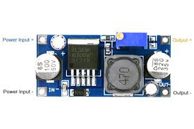
Pin Configuration and Descriptions
| Pin Name | Description |
|---|---|
| VIN | Input voltage terminal (connect to power source) |
| GND | Ground terminal (common ground for input and output) |
| VOUT | Output voltage terminal (connect to load) |
| EN (optional) | Enable pin (used to turn the module on/off) |
Usage Instructions
How to Use the Boost Converter in a Circuit
Connect the Input Voltage (VIN):
- Attach the positive terminal of your power source to the VIN pin.
- Connect the negative terminal of your power source to the GND pin.
Set the Desired Output Voltage (if adjustable):
- Many Boost Converter modules include a potentiometer for adjusting the output voltage.
- Use a multimeter to measure the output voltage at the VOUT pin while turning the potentiometer until the desired voltage is achieved.
Connect the Load:
- Attach the positive terminal of your load to the VOUT pin.
- Connect the negative terminal of your load to the GND pin.
Power On the Circuit:
- Ensure the input voltage is within the specified range of the Boost Converter.
- Turn on the power source, and the Boost Converter will step up the voltage to the desired level.
Important Considerations and Best Practices
- Input Voltage Range: Ensure the input voltage is within the specified range of the Boost Converter. Exceeding this range may damage the module.
- Output Current Limit: Do not exceed the maximum output current rating of the module, as this can lead to overheating or failure.
- Heat Dissipation: For high-power applications, consider adding a heatsink or active cooling to prevent overheating.
- Ripple and Noise: Use additional capacitors at the input and output terminals to reduce voltage ripple and noise.
- Polarity Protection: Double-check the polarity of your connections to avoid damaging the module.
Example: Using a Boost Converter with an Arduino UNO
Below is an example of using a Boost Converter to power an Arduino UNO with a 9V output from a 5V input source.
Circuit Connections
- Connect the 5V power source to the VIN and GND pins of the Boost Converter.
- Adjust the Boost Converter's output voltage to 9V using the potentiometer.
- Connect the VOUT pin of the Boost Converter to the Arduino UNO's VIN pin.
- Connect the GND pin of the Boost Converter to the Arduino UNO's GND pin.
Arduino Code Example
// Example code to blink an LED connected to pin 13 of the Arduino UNO
// Ensure the Arduino is powered via the Boost Converter (9V output).

void setup() {
  pinMode(13, OUTPUT); // Set pin 13 as an output
}

void loop() {
  digitalWrite(13, HIGH); // Turn the LED on
  delay(1000);            // Wait for 1 second
  digitalWrite(13, LOW);  // Turn the LED off
  delay(1000);            // Wait for 1 second
}
Troubleshooting and FAQs
Common Issues and Solutions
No Output Voltage:
- Cause: Incorrect wiring or insufficient input voltage.
- Solution: Verify all connections and ensure the input voltage is within the specified range.
Output Voltage is Unstable:
- Cause: Insufficient input power or high ripple.
- Solution: Add capacitors to the input and output terminals to stabilize the voltage.
Module Overheating:
- Cause: Exceeding the maximum current rating or poor heat dissipation.
- Solution: Reduce the load current or add a heatsink to the module.
Output Voltage Not Adjustable:
- Cause: Faulty potentiometer or incorrect adjustment.
- Solution: Check the potentiometer for damage and adjust it carefully while monitoring the output voltage.
FAQs
Q: Can I use a Boost Converter to power a microcontroller directly?
A: Yes, as long as the output voltage and current are within the operating range of the microcontroller.
Q: What happens if I reverse the input polarity?
A: Most Boost Converters do not have built-in polarity protection. Reversing the polarity may damage the module. Always double-check your connections.
Q: Can I use a Boost Converter with a battery?
A: Yes, Boost Converters are commonly used with batteries to step up their voltage. Ensure the battery can supply sufficient current for your application.
Q: How do I reduce noise in the output voltage?
A: Add low ESR capacitors to the output terminals and ensure proper grounding in your circuit.
This concludes the documentation for the Boost Converter. Follow the guidelines above for safe and efficient operation!