Cirkit Designer Logo
Cirkit Designer
Your all-in-one circuit design IDE
Home / 
Component Documentation

How to Use XM 15B: Examples, Pinouts, and Specs

Image of XM 15B
Cirkit Designer LogoDesign with XM 15B in Cirkit Designer

Introduction

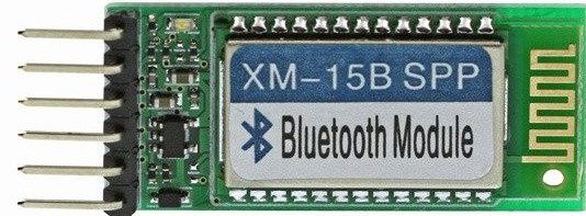
The XM 15B is a versatile electronic component widely utilized in communication systems. Renowned for its reliability and high performance, the XM 15B excels in signal processing applications, making it a popular choice for both industrial and consumer electronics. Its robust design and adaptability allow it to function effectively in a variety of environments, ensuring consistent operation in demanding scenarios.

Explore Projects Built with XM 15B

Use Cirkit Designer to design, explore, and prototype these projects online. Some projects support real-time simulation. Click "Open Project" to start designing instantly!
Satellite-Based Timing and Navigation System with SDR and Atomic Clock Synchronization
Image of GPS 시스템 측정 구성도_Confirm: A project utilizing XM 15B in a practical application
This circuit appears to be a complex system involving power supply management, GPS and timing synchronization, and data communication. It includes a SI-TEX G1 Satellite Compass for GPS data, an XHTF1021 Atomic Rubidium Clock for precise timing, and Ettus USRP B200 units for software-defined radio communication. Power is supplied through various SMPS units and distributed via terminal blocks and DC jacks. Data communication is facilitated by Beelink MINI S12 N95 computers, RS232 splitters, and a 1000BASE-T Media Converter for network connectivity. RF Directional Couplers are used to interface antennas with the USRP units, and the entire system is likely contained within cases for protection and organization.
Cirkit Designer LogoOpen Project in Cirkit Designer
Battery-Powered Adjustable Voltage Regulator with Li-ion 18650 Batteries and BMS
Image of mini ups: A project utilizing XM 15B in a practical application
This circuit is a power management system that uses four Li-ion 18650 batteries connected to a 2S 30A BMS for battery management and protection. The system includes step-up and step-down voltage regulators to provide adjustable output voltages, controlled by a rocker switch, and multiple DC jacks for power input and output.
Cirkit Designer LogoOpen Project in Cirkit Designer
Solar-Powered GSM/GPRS+GPS Tracker with Seeeduino XIAO
Image of SOS System : A project utilizing XM 15B in a practical application
This circuit features an Ai Thinker A9G development board for GSM/GPRS and GPS/BDS connectivity, interfaced with a Seeeduino XIAO microcontroller for control and data processing. A solar cell, coupled with a TP4056 charging module, charges a 3.3V battery, which powers the system through a 3.3V regulator ensuring stable operation. The circuit likely serves for remote data communication and location tracking, with the capability to be powered by renewable energy and interfaced with additional sensors or input devices via the Seeeduino XIAO.
Cirkit Designer LogoOpen Project in Cirkit Designer
Battery-Powered UPS System with Waveshare UPS 3S and Solar Charger
Image of Copy of s: A project utilizing XM 15B in a practical application
This circuit is a power management system that integrates a 12V power supply, a solar charger power bank, and multiple Li-ion batteries to provide a stable power output. The Waveshare UPS 3S manages the input from the power sources and batteries, ensuring continuous power delivery. The MRB045 module is used to interface the solar charger with the rest of the system.
Cirkit Designer LogoOpen Project in Cirkit Designer

Explore Projects Built with XM 15B

Use Cirkit Designer to design, explore, and prototype these projects online. Some projects support real-time simulation. Click "Open Project" to start designing instantly!
Image of GPS 시스템 측정 구성도_Confirm: A project utilizing XM 15B in a practical application
Satellite-Based Timing and Navigation System with SDR and Atomic Clock Synchronization
This circuit appears to be a complex system involving power supply management, GPS and timing synchronization, and data communication. It includes a SI-TEX G1 Satellite Compass for GPS data, an XHTF1021 Atomic Rubidium Clock for precise timing, and Ettus USRP B200 units for software-defined radio communication. Power is supplied through various SMPS units and distributed via terminal blocks and DC jacks. Data communication is facilitated by Beelink MINI S12 N95 computers, RS232 splitters, and a 1000BASE-T Media Converter for network connectivity. RF Directional Couplers are used to interface antennas with the USRP units, and the entire system is likely contained within cases for protection and organization.
Cirkit Designer LogoOpen Project in Cirkit Designer
Image of mini ups: A project utilizing XM 15B in a practical application
Battery-Powered Adjustable Voltage Regulator with Li-ion 18650 Batteries and BMS
This circuit is a power management system that uses four Li-ion 18650 batteries connected to a 2S 30A BMS for battery management and protection. The system includes step-up and step-down voltage regulators to provide adjustable output voltages, controlled by a rocker switch, and multiple DC jacks for power input and output.
Cirkit Designer LogoOpen Project in Cirkit Designer
Image of SOS System : A project utilizing XM 15B in a practical application
Solar-Powered GSM/GPRS+GPS Tracker with Seeeduino XIAO
This circuit features an Ai Thinker A9G development board for GSM/GPRS and GPS/BDS connectivity, interfaced with a Seeeduino XIAO microcontroller for control and data processing. A solar cell, coupled with a TP4056 charging module, charges a 3.3V battery, which powers the system through a 3.3V regulator ensuring stable operation. The circuit likely serves for remote data communication and location tracking, with the capability to be powered by renewable energy and interfaced with additional sensors or input devices via the Seeeduino XIAO.
Cirkit Designer LogoOpen Project in Cirkit Designer
Image of Copy of s: A project utilizing XM 15B in a practical application
Battery-Powered UPS System with Waveshare UPS 3S and Solar Charger
This circuit is a power management system that integrates a 12V power supply, a solar charger power bank, and multiple Li-ion batteries to provide a stable power output. The Waveshare UPS 3S manages the input from the power sources and batteries, ensuring continuous power delivery. The MRB045 module is used to interface the solar charger with the rest of the system.
Cirkit Designer LogoOpen Project in Cirkit Designer

Common Applications and Use Cases

  • Signal amplification and processing in communication systems
  • Noise reduction in audio and RF circuits
  • Data transmission and reception in wireless devices
  • Integration into IoT devices for enhanced signal handling
  • Use in industrial automation systems for reliable communication

Technical Specifications

Key Technical Details

Parameter Value
Operating Voltage 3.3V to 5V
Maximum Current 50 mA
Signal Frequency Range 10 Hz to 1 MHz
Operating Temperature -40°C to +85°C
Power Consumption < 250 mW
Package Type DIP-8 or SMD

Pin Configuration and Descriptions

Pin Number Pin Name Description
1 VCC Power supply input (3.3V to 5V)
2 GND Ground connection
3 IN+ Non-inverting signal input
4 IN- Inverting signal input
5 OUT Signal output
6 NC No connection (leave unconnected)
7 ENABLE Enable/disable control (active high)
8 NC No connection (leave unconnected)

Usage Instructions

How to Use the XM 15B in a Circuit

  1. Power Supply: Connect the VCC pin to a stable power source (3.3V to 5V) and the GND pin to the ground of the circuit.
  2. Signal Input: Feed the input signal to the IN+ and IN- pins. For single-ended signals, connect IN- to GND.
  3. Signal Output: The processed signal will be available at the OUT pin. Connect this pin to the next stage of your circuit.
  4. Enable Control: Use the ENABLE pin to activate or deactivate the component. Pull the pin high (logic 1) to enable the XM 15B, or pull it low (logic 0) to disable it.

Important Considerations and Best Practices

  • Decoupling Capacitors: Place a 0.1 µF ceramic capacitor close to the VCC pin to filter out noise and ensure stable operation.
  • Signal Integrity: Use short and shielded wires for the input and output signals to minimize noise and interference.
  • Thermal Management: Ensure adequate ventilation or heat dissipation if the component operates near its maximum power rating.
  • Unused Pins: Leave the NC (No Connection) pins unconnected to avoid unintended behavior.

Example: Using XM 15B with Arduino UNO

The XM 15B can be easily interfaced with an Arduino UNO for signal processing tasks. Below is an example code snippet to demonstrate its usage:

// Example: Using XM 15B with Arduino UNO
// This code reads an analog signal processed by the XM 15B and outputs the
// result to the serial monitor.

const int signalInputPin = A0; // Connect XM 15B OUT pin to Arduino A0
const int enablePin = 7;       // Connect XM 15B ENABLE pin to Arduino digital pin 7

void setup() {
  pinMode(enablePin, OUTPUT);  // Set ENABLE pin as output
  digitalWrite(enablePin, HIGH); // Enable the XM 15B by setting ENABLE pin high
  Serial.begin(9600);          // Initialize serial communication at 9600 baud
}

void loop() {
  int signalValue = analogRead(signalInputPin); // Read the processed signal
  Serial.print("Signal Value: ");
  Serial.println(signalValue); // Output the signal value to the serial monitor
  delay(500);                  // Wait for 500 ms before the next reading
}

Troubleshooting and FAQs

Common Issues and Solutions

  1. No Output Signal:

    • Ensure the ENABLE pin is pulled high to activate the XM 15B.
    • Verify that the power supply voltage is within the specified range (3.3V to 5V).
    • Check the input signal connections to the IN+ and IN- pins.
  2. Excessive Noise in Output:

    • Use decoupling capacitors near the VCC pin to filter power supply noise.
    • Ensure proper grounding and minimize the length of signal wires.
  3. Overheating:

    • Confirm that the power consumption does not exceed the specified limit of 250 mW.
    • Improve ventilation or add a heatsink if necessary.
  4. Component Not Responding:

    • Double-check the pin connections and ensure no pins are left floating (except NC pins).
    • Test the ENABLE pin functionality by toggling it between high and low states.

FAQs

Q1: Can the XM 15B handle AC signals?
A1: Yes, the XM 15B is designed to process both AC and DC signals within its frequency range of 10 Hz to 1 MHz.

Q2: What happens if the ENABLE pin is left floating?
A2: If the ENABLE pin is left floating, the behavior of the XM 15B may be unpredictable. It is recommended to pull the pin high or low as needed.

Q3: Is the XM 15B suitable for battery-powered devices?
A3: Yes, the XM 15B has low power consumption (< 250 mW), making it suitable for battery-powered applications.

Q4: Can I use the XM 15B with a 12V power supply?
A4: No, the XM 15B operates within a voltage range of 3.3V to 5V. Using a 12V supply may damage the component. Use a voltage regulator if needed.