How to Use L298N: Examples, Pinouts, and Specs
Introduction
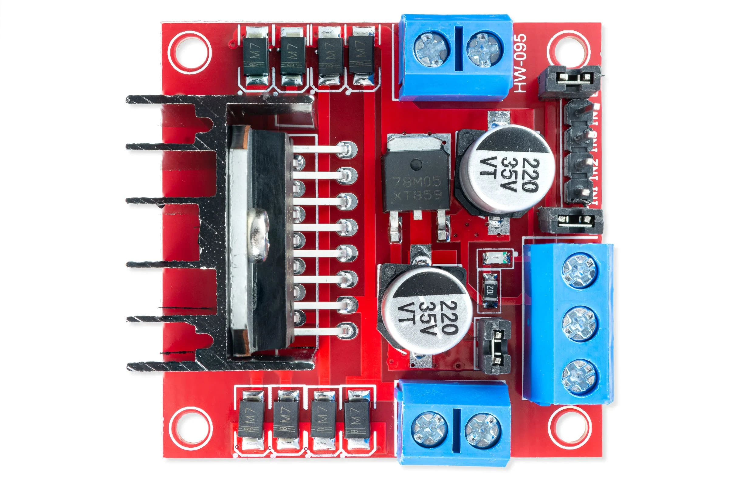
The L298N is a dual H-bridge motor driver IC manufactured by STMicroelectronics. It is designed to control the direction and speed of DC motors and stepper motors. With the ability to drive two motors simultaneously, the L298N is widely used in robotics, automation, and other motor control applications. Its robust design allows it to handle up to 2A per channel and operate at voltages up to 46V, making it suitable for a variety of medium-power motor control tasks.
Explore Projects Built with L298N
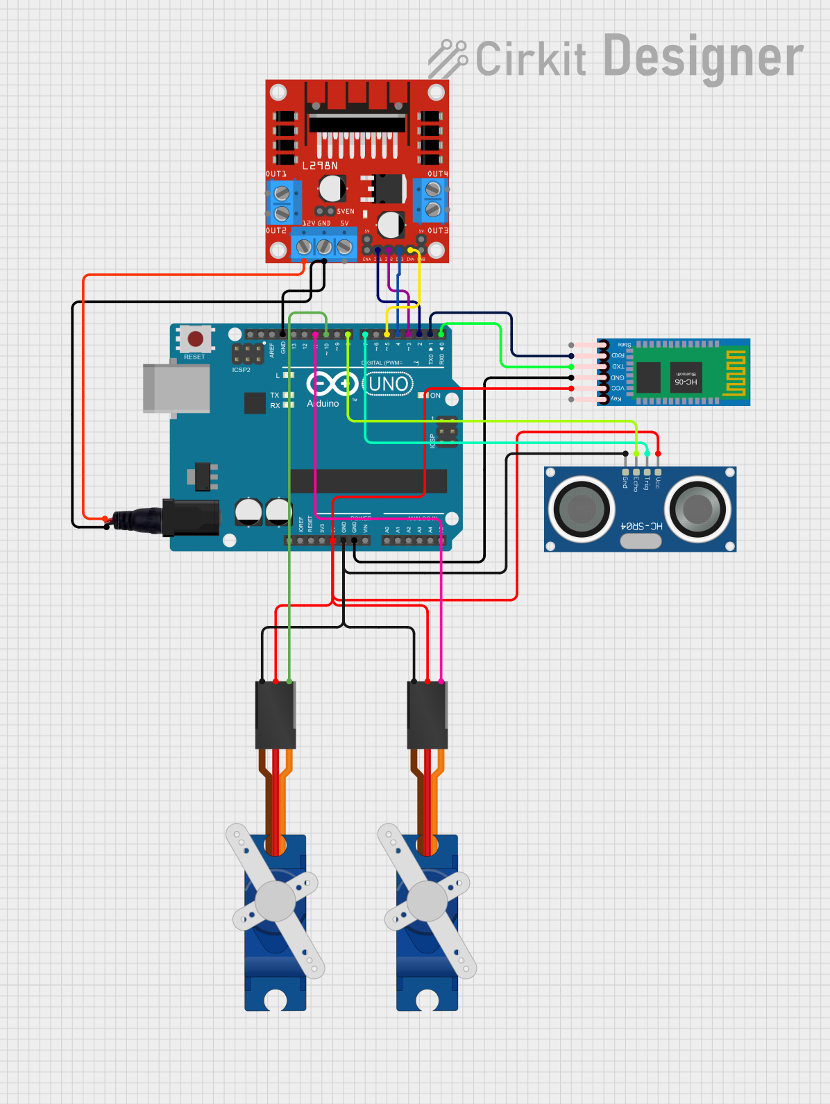
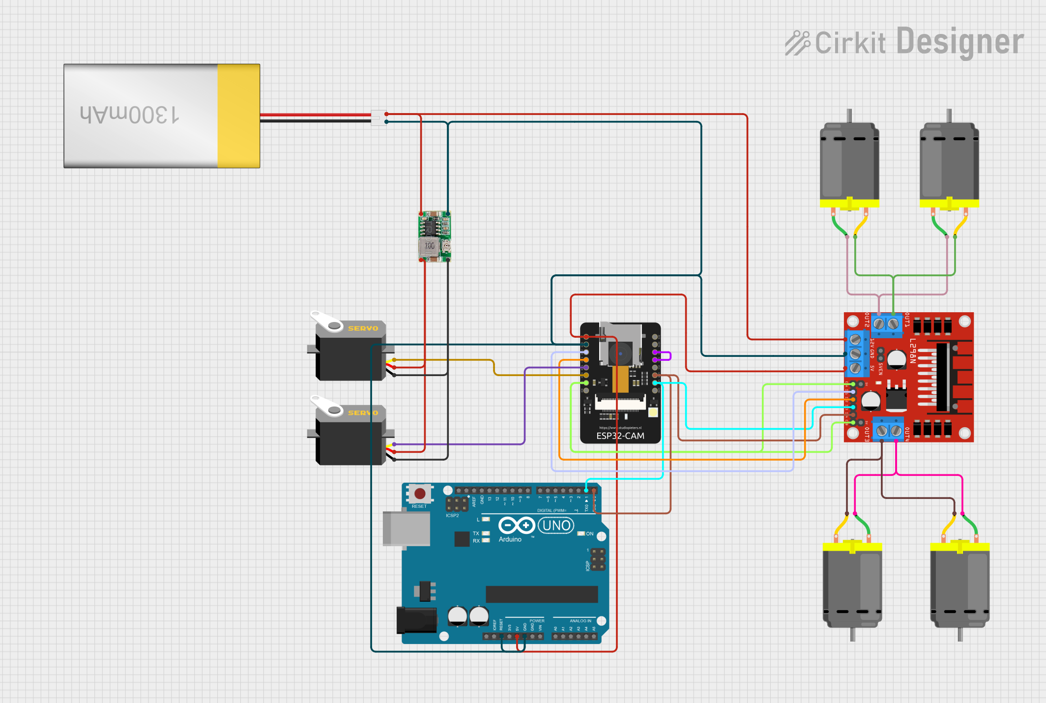
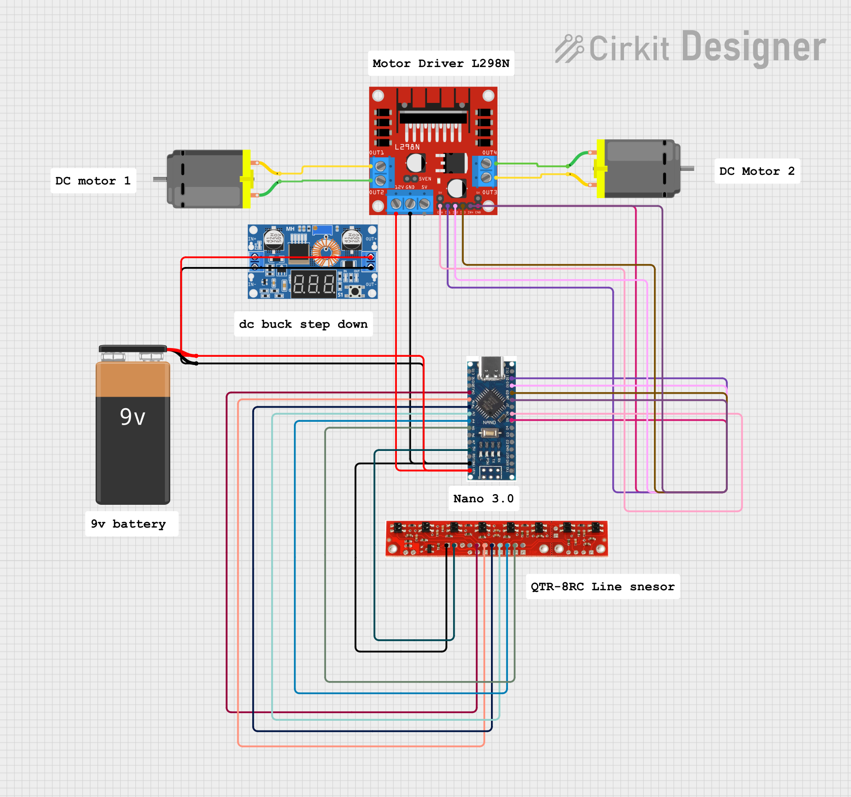

Explore Projects Built with L298N
Common Applications
- Robotics (e.g., controlling wheels or tracks)
- Automation systems
- Stepper motor control
- Conveyor belts
- DIY electronics projects
- Educational kits for motor control
Technical Specifications
The L298N is a versatile motor driver IC with the following key specifications:
| Parameter | Value |
|---|---|
| Manufacturer | STMicroelectronics |
| Part Number | L298N |
| Operating Voltage Range | 4.5V to 46V |
| Maximum Output Current | 2A per channel (continuous) |
| Peak Output Current | 3A per channel (non-repetitive) |
| Logic Voltage Range | 4.5V to 7V |
| Power Dissipation | 25W (with proper heat sinking) |
| Control Logic Levels | TTL-compatible |
| Operating Temperature | -25°C to +130°C |
| Package Type | Multiwatt15 or PowerSO20 |
Pin Configuration and Descriptions
The L298N IC has 15 pins in the Multiwatt15 package. Below is the pinout and description:
| Pin Number | Pin Name | Description |
|---|---|---|
| 1 | Enable A | Enables or disables the output for Motor A. High = Enabled, Low = Disabled. |
| 2 | Input 1 | Logic input to control Motor A (connected to microcontroller or logic circuit). |
| 3 | Input 2 | Logic input to control Motor A (connected to microcontroller or logic circuit). |
| 4 | Output 1 | Output terminal for Motor A. |
| 5 | Output 2 | Output terminal for Motor A. |
| 6 | VSS | Logic supply voltage (4.5V to 7V). |
| 7 | VS | Motor supply voltage (up to 46V). |
| 8 | GND | Ground connection. |
| 9 | GND | Ground connection. |
| 10 | Output 3 | Output terminal for Motor B. |
| 11 | Output 4 | Output terminal for Motor B. |
| 12 | Input 3 | Logic input to control Motor B (connected to microcontroller or logic circuit). |
| 13 | Input 4 | Logic input to control Motor B (connected to microcontroller or logic circuit). |
| 14 | Enable B | Enables or disables the output for Motor B. High = Enabled, Low = Disabled. |
| 15 | Sense A/B | Current sensing pins for Motor A and Motor B (optional, for monitoring). |
Usage Instructions
The L298N can be used to control two DC motors or a single stepper motor. Below are the steps and considerations for using the L298N in a circuit.
Connecting the L298N
Power Supply:
- Connect the motor power supply (up to 46V) to the VS pin.
- Connect the logic power supply (4.5V to 7V) to the VSS pin.
- Ensure a common ground connection between the motor driver and the microcontroller.
Motor Connections:
- Connect the motor terminals to the Output 1/2 pins for Motor A and Output 3/4 pins for Motor B.
Control Inputs:
- Use the Input 1/2 pins to control Motor A and Input 3/4 pins to control Motor B.
- Apply logic HIGH or LOW signals to these pins to set the motor direction.
Enable Pins:
- Set the Enable A and Enable B pins HIGH to enable the motors.
- Use PWM signals on these pins to control motor speed.
Optional Current Sensing:
- Connect the Sense A/B pins to a resistor to monitor motor current.
Example: Controlling a DC Motor with Arduino UNO
Below is an example Arduino sketch to control a DC motor using the L298N:
// Define L298N control pins
const int enableA = 9;  // PWM pin for Motor A speed control
const int input1 = 8;   // Direction control pin 1 for Motor A
const int input2 = 7;   // Direction control pin 2 for Motor A

void setup() {
  // Set pin modes
  pinMode(enableA, OUTPUT);
  pinMode(input1, OUTPUT);
  pinMode(input2, OUTPUT);

  // Initialize motor in stopped state
  digitalWrite(input1, LOW);
  digitalWrite(input2, LOW);
  analogWrite(enableA, 0);  // Set speed to 0
}

void loop() {
  // Rotate motor forward at 50% speed
  digitalWrite(input1, HIGH);
  digitalWrite(input2, LOW);
  analogWrite(enableA, 128);  // PWM value (0-255)

  delay(2000);  // Run for 2 seconds

  // Rotate motor backward at 75% speed
  digitalWrite(input1, LOW);
  digitalWrite(input2, HIGH);
  analogWrite(enableA, 192);  // PWM value (0-255)

  delay(2000);  // Run for 2 seconds

  // Stop the motor
  digitalWrite(input1, LOW);
  digitalWrite(input2, LOW);
  analogWrite(enableA, 0);  // Set speed to 0

  delay(2000);  // Wait for 2 seconds
}
Best Practices
- Use a heat sink on the L298N to prevent overheating during high-current operation.
- Add decoupling capacitors near the power supply pins to reduce noise.
- Use diodes across the motor terminals to protect against back EMF.
- Ensure the motor's current rating does not exceed the L298N's maximum current capacity.
Troubleshooting and FAQs
Common Issues
Motor not spinning:
- Check the power supply connections to the VS and VSS pins.
- Ensure the Enable pins are set HIGH.
- Verify the logic inputs are correctly configured.
Overheating:
- Ensure a heat sink is attached to the L298N.
- Check that the motor's current does not exceed 2A per channel.
Inconsistent motor speed:
- Verify the PWM signal is stable and within the correct range.
- Check for loose connections or noise in the power supply.
No response from the motor:
- Ensure the ground of the motor driver is connected to the microcontroller's ground.
- Test the motor independently to confirm it is functional.
FAQs
Q: Can the L298N drive stepper motors?
A: Yes, the L298N can drive a bipolar stepper motor by controlling the two H-bridges. Use a stepper motor library for precise control.
Q: What is the maximum voltage the L298N can handle?
A: The L298N can handle up to 46V on the motor supply pin (VS).
Q: Do I need external diodes with the L298N?
A: The L298N has internal diodes for back EMF protection, but external diodes can be added for additional safety in high-power applications.
Q: Can I use the L298N with a 3.3V microcontroller?
A: The L298N requires a logic voltage of at least 4.5V, so a level shifter or 5V logic source is needed for compatibility with 3.3V systems.