How to Use PLC SCHNEIDER TM221CE40R: Examples, Pinouts, and Specs
Introduction
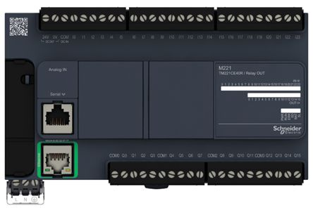
The Schneider TM221CE40R is a programmable logic controller (PLC) designed for automation and control applications. It features a compact design, integrated I/O (input/output), and supports various communication protocols, making it suitable for small to medium-sized industrial tasks. This PLC is part of Schneider Electric's Modicon M221 series, known for its reliability, flexibility, and ease of use.
Explore Projects Built with PLC SCHNEIDER TM221CE40R


Explore Projects Built with PLC SCHNEIDER TM221CE40R
Common Applications and Use Cases
- Industrial automation and process control
- Machine control in manufacturing environments
- Building automation systems
- Conveyor belt systems
- Monitoring and controlling HVAC systems
- Small-scale SCADA (Supervisory Control and Data Acquisition) systems
Technical Specifications
Key Technical Details
| Specification | Value |
|---|---|
| Model Number | TM221CE40R |
| Supply Voltage | 24 V DC |
| Number of Digital Inputs | 24 |
| Number of Digital Outputs | 16 (Relay outputs) |
| Communication Protocols | Ethernet, Modbus TCP, Serial (RS485) |
| Programming Software | EcoStruxure Machine Expert - Basic |
| Memory | 256 KB for application storage |
| Operating Temperature Range | -10°C to +55°C |
| Dimensions | 150 x 95 x 86 mm |
| Mounting | DIN rail or panel mounting |
Pin Configuration and Descriptions
The TM221CE40R has multiple I/O terminals for connecting sensors, actuators, and communication interfaces. Below is a summary of the pin configuration:
Digital Inputs
| Pin Number | Description | Voltage Range |
|---|---|---|
| DI1-DI24 | Digital Inputs 1 to 24 | 0-24 V DC |
Digital Outputs
| Pin Number | Description | Output Type |
|---|---|---|
| DO1-DO16 | Digital Outputs 1 to 16 | Relay (NO/NC) |
Communication Ports
| Port | Description | Protocol Supported |
|---|---|---|
| Ethernet | Ethernet communication port | Modbus TCP |
| Serial | RS485 communication port | Modbus RTU |
Usage Instructions
How to Use the TM221CE40R in a Circuit
- Power Supply: Connect a 24 V DC power supply to the PLC's power input terminals. Ensure the power supply is stable and within the specified voltage range.
- Digital Inputs: Connect sensors or switches to the digital input terminals (DI1-DI24). Ensure the input voltage does not exceed 24 V DC.
- Digital Outputs: Connect actuators, relays, or other devices to the digital output terminals (DO1-DO16). Verify the output load is within the relay's rated capacity.
- Communication: Use the Ethernet or RS485 port to connect the PLC to a network or other devices. Configure the communication settings (e.g., IP address, baud rate) using the EcoStruxure Machine Expert - Basic software.
- Programming: Write and upload your control logic using the EcoStruxure Machine Expert - Basic software. The software supports ladder logic, function block diagrams, and structured text programming.
Important Considerations and Best Practices
- Always verify the wiring connections before powering on the PLC to avoid damage.
- Use proper shielding and grounding for communication cables to minimize interference.
- Regularly back up your PLC program to prevent data loss.
- Ensure the PLC is installed in a well-ventilated area to prevent overheating.
- Follow all safety guidelines and standards for industrial automation systems.
Example Code for Modbus Communication with Arduino UNO
Below is an example of how to communicate with the TM221CE40R using Modbus RTU and an Arduino UNO:
#include <ModbusMaster.h>

// Instantiate ModbusMaster object
ModbusMaster node;

void setup() {
  Serial.begin(9600); // Initialize serial communication at 9600 baud
  node.begin(1, Serial); // Set Modbus slave ID to 1 and use Serial for communication
}

void loop() {
  uint8_t result;
  uint16_t data;

  // Read holding register 40001 from the PLC
  result = node.readHoldingRegisters(0x0000, 1);

  if (result == node.ku8MBSuccess) {
    data = node.getResponseBuffer(0); // Get the value of the register
    Serial.print("Register Value: ");
    Serial.println(data); // Print the value to the serial monitor
  } else {
    Serial.println("Failed to read register"); // Print error message if read fails
  }

  delay(1000); // Wait 1 second before the next read
}
Notes:
- Use a TTL-to-RS485 converter to connect the Arduino UNO to the TM221CE40R's RS485 port.
- Configure the PLC's Modbus settings (e.g., slave ID, baud rate) to match the Arduino code.
Troubleshooting and FAQs
Common Issues and Solutions
PLC Not Powering On
- Cause: Incorrect or unstable power supply.
- Solution: Verify the power supply voltage is 24 V DC and properly connected.
Digital Inputs Not Responding
- Cause: Faulty wiring or incompatible input voltage.
- Solution: Check the wiring and ensure the input voltage is within the 0-24 V DC range.
Communication Failure
- Cause: Incorrect communication settings or faulty cables.
- Solution: Verify the communication protocol, baud rate, and cable connections. Use proper shielding for RS485 cables.
Program Not Executing
- Cause: Errors in the PLC program or improper upload.
- Solution: Debug the program using the EcoStruxure Machine Expert - Basic software and re-upload it.
FAQs
Q: Can the TM221CE40R be used with third-party sensors and actuators?
A: Yes, as long as the sensors and actuators are compatible with the PLC's input/output specifications.
Q: What is the maximum cable length for RS485 communication?
A: The maximum recommended cable length for RS485 is 1200 meters, depending on the baud rate and cable quality.
Q: Is the TM221CE40R suitable for outdoor use?
A: No, the PLC is designed for indoor use in a controlled environment. Use an appropriate enclosure for outdoor applications.
Q: Can I expand the I/O of the TM221CE40R?
A: Yes, the TM221CE40R supports expansion modules to increase the number of I/O points.
This documentation provides a comprehensive guide to using the Schneider TM221CE40R PLC effectively. For further assistance, refer to the official Schneider Electric user manual or contact technical support.