How to Use 5A 3V-14V Dual DC Motor Drive Module: Examples, Pinouts, and Specs
Introduction
The 5A 3V-14V Dual DC Motor Drive Module is a versatile motor driver designed to control two DC motors simultaneously. It supports bidirectional control and speed regulation, making it ideal for robotics, automation systems, and other motor-driven applications. With a maximum current capacity of 5A per channel and an operating voltage range of 3V to 14V, this module is suitable for a wide variety of low- to medium-power motors.
Explore Projects Built with 5A 3V-14V Dual DC Motor Drive Module


Explore Projects Built with 5A 3V-14V Dual DC Motor Drive Module
Common Applications
- Robotics and mobile platforms
- Conveyor belts and automated systems
- Remote-controlled vehicles
- DIY electronics projects
- Motorized mechanisms requiring speed and direction control
Technical Specifications
Key Details
- Operating Voltage: 3V to 14V DC
- Maximum Current: 5A per motor channel
- Number of Channels: 2 (supports two DC motors)
- Control Mode: PWM (Pulse Width Modulation) for speed control
- Direction Control: Forward and reverse for each motor
- Logic Voltage: 3.3V or 5V (compatible with most microcontrollers)
- Dimensions: Typically compact, varies by manufacturer
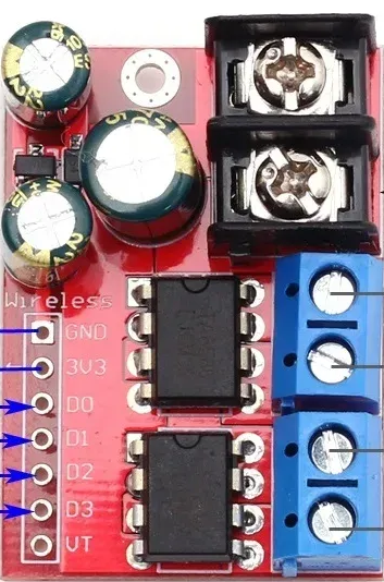
Pin Configuration and Descriptions
The module typically has the following pin layout:
| Pin Name | Description |
|---|---|
VCC |
Power supply for the motors (3V to 14V DC). |
GND |
Ground connection for the module. |
IN1 |
Control input for Motor A direction (logic HIGH/LOW). |
IN2 |
Control input for Motor A direction (logic HIGH/LOW). |
IN3 |
Control input for Motor B direction (logic HIGH/LOW). |
IN4 |
Control input for Motor B direction (logic HIGH/LOW). |
ENA |
PWM input for speed control of Motor A. |
ENB |
PWM input for speed control of Motor B. |
OUT1 |
Output terminal for Motor A. |
OUT2 |
Output terminal for Motor A. |
OUT3 |
Output terminal for Motor B. |
OUT4 |
Output terminal for Motor B. |
Note: Some modules may include additional pins for features like current sensing or enable/disable functionality. Always refer to the specific datasheet for your module.
Usage Instructions
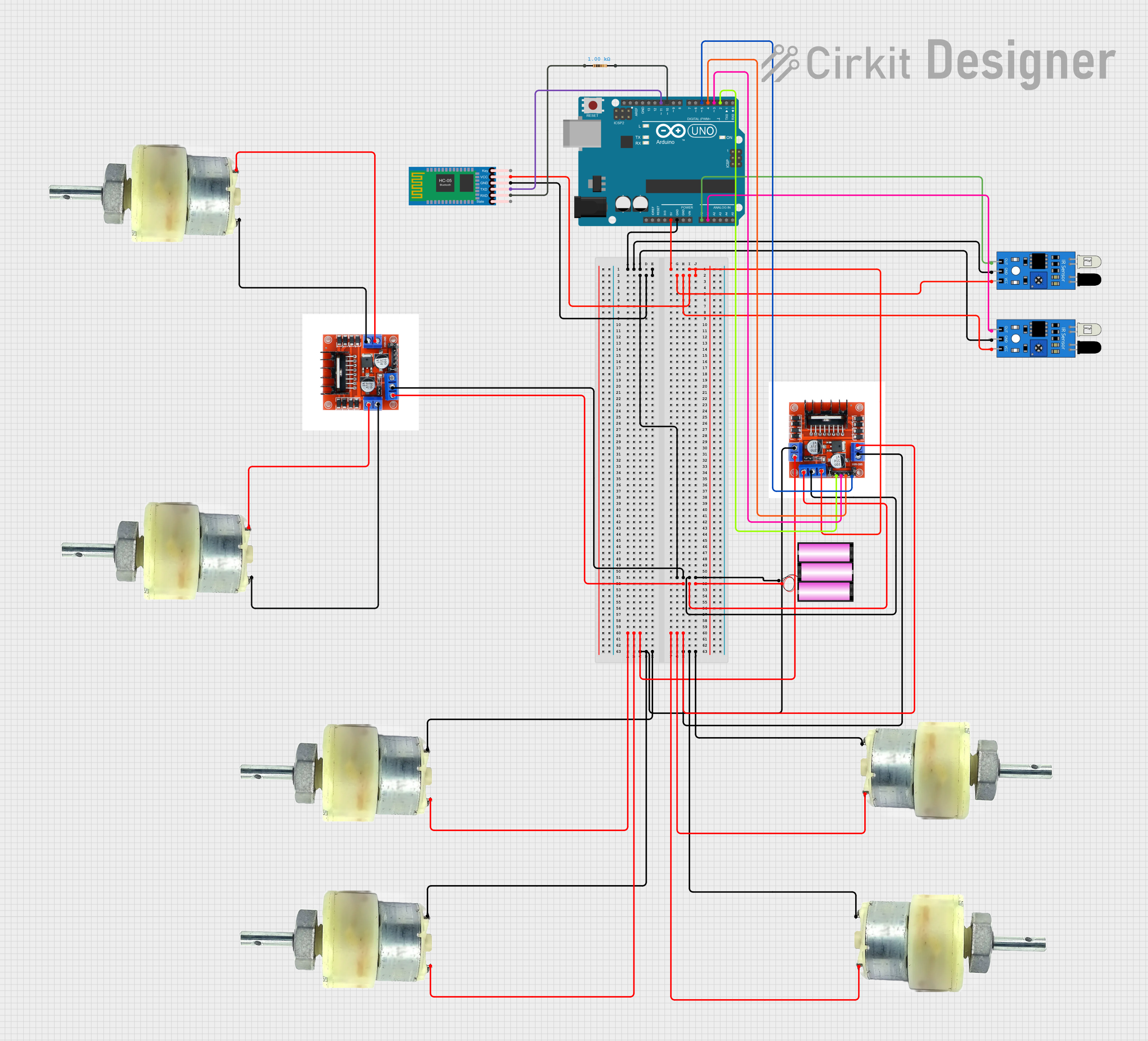
How to Use the Module in a Circuit
- Power the Module: Connect the
VCCpin to a DC power source (3V-14V) and theGNDpin to ground. - Connect the Motors: Attach the two terminals of Motor A to
OUT1andOUT2, and Motor B toOUT3andOUT4. - Control Inputs:
- Use
IN1andIN2to control the direction of Motor A. - Use
IN3andIN4to control the direction of Motor B. - Apply a PWM signal to
ENAandENBto control the speed of Motor A and Motor B, respectively.
- Use
- Logic Voltage: Ensure the control signals (
IN1,IN2,IN3,IN4,ENA,ENB) are compatible with the module's logic voltage (3.3V or 5V).
Example Arduino Code
Below is an example of how to control two DC motors using an Arduino UNO and the 5A Dual DC Motor Drive Module:
// Define motor control pins
#define IN1 7  // Motor A direction control pin 1
#define IN2 6  // Motor A direction control pin 2
#define ENA 5  // Motor A speed control (PWM)
#define IN3 4  // Motor B direction control pin 1
#define IN4 3  // Motor B direction control pin 2
#define ENB 2  // Motor B speed control (PWM)

void setup() {
  // Set motor control pins as outputs
  pinMode(IN1, OUTPUT);
  pinMode(IN2, OUTPUT);
  pinMode(ENA, OUTPUT);
  pinMode(IN3, OUTPUT);
  pinMode(IN4, OUTPUT);
  pinMode(ENB, OUTPUT);
}

void loop() {
  // Motor A: Forward at 50% speed
  digitalWrite(IN1, HIGH);  // Set direction
  digitalWrite(IN2, LOW);
  analogWrite(ENA, 128);    // Set speed (0-255)

  // Motor B: Reverse at 75% speed
  digitalWrite(IN3, LOW);   // Set direction
  digitalWrite(IN4, HIGH);
  analogWrite(ENB, 192);    // Set speed (0-255)

  delay(5000);              // Run motors for 5 seconds

  // Stop both motors
  analogWrite(ENA, 0);      // Stop Motor A
  analogWrite(ENB, 0);      // Stop Motor B
  delay(2000);              // Wait for 2 seconds
}
Important Considerations
- Power Supply: Ensure the power supply can provide sufficient current for both motors. Exceeding the module's current rating (5A per channel) may damage the module.
- Heat Dissipation: If operating at high currents, consider adding a heat sink or active cooling to prevent overheating.
- PWM Frequency: Use a PWM frequency compatible with the module and your motors to avoid noise or inefficiency.
- Motor Voltage: Ensure the motor voltage matches the power supply voltage.
Troubleshooting and FAQs
Common Issues
Motors Not Running:
- Check the power supply voltage and current.
- Verify the control signals (
IN1,IN2,IN3,IN4,ENA,ENB) are correctly configured. - Ensure the motor connections (
OUT1,OUT2,OUT3,OUT4) are secure.
Overheating:
- Ensure the current draw does not exceed 5A per channel.
- Add a heat sink or fan if necessary.
Erratic Motor Behavior:
- Check for loose connections or poor solder joints.
- Verify the PWM signal is stable and within the correct frequency range.
FAQs
Q: Can I use this module with a 3.3V microcontroller?
A: Yes, the module is compatible with both 3.3V and 5V logic levels. Ensure the control signals match the microcontroller's logic voltage.
Q: Can I control only one motor with this module?
A: Yes, you can use just one channel (e.g., IN1, IN2, ENA) to control a single motor.
Q: What happens if I reverse the power supply polarity?
A: Reversing the polarity may damage the module. Always double-check your connections before powering the module.
Q: Can I use this module to control stepper motors?
A: No, this module is designed for DC motors. Use a dedicated stepper motor driver for stepper motors.