Introduction
The MPU6050 Ankle is a motion tracking sensor that integrates a 3-axis gyroscope and a 3-axis accelerometer into a single chip. This compact and versatile sensor is widely used in wearable devices, robotics, and IoT applications to monitor movement, orientation, and angular velocity. Its ability to measure both linear acceleration and rotational motion makes it ideal for applications such as fitness tracking, gait analysis, and stabilization systems.
Common Applications:
- Wearable devices for motion tracking (e.g., fitness bands, smart shoes)
- Robotics for orientation and balance control
- Gait analysis in healthcare and sports
- Stabilization systems for drones and cameras
- Virtual reality (VR) and augmented reality (AR) systems
Technical Specifications
The MPU6050 Ankle is designed to provide accurate motion tracking with minimal power consumption. Below are its key technical details:
Key Specifications:
Pin Configuration:
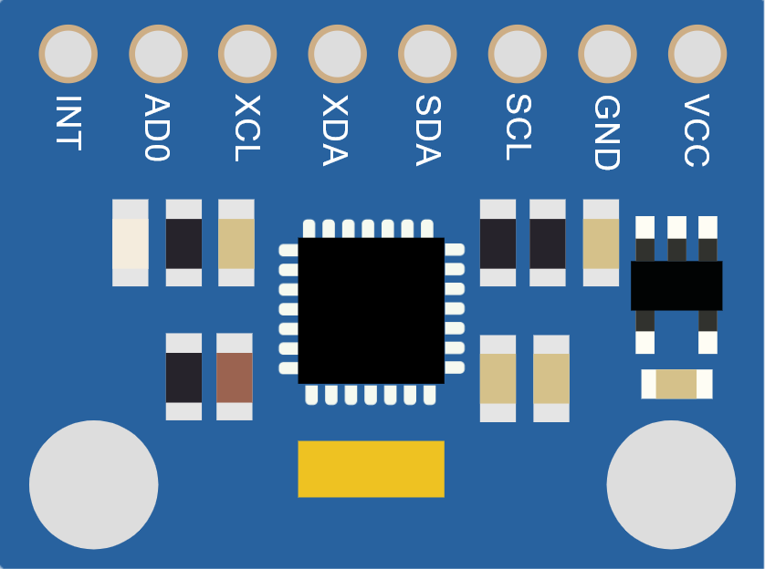
The MPU6050 Ankle has 8 pins, as described in the table below:
Usage Instructions
How to Use the MPU6050 Ankle in a Circuit:
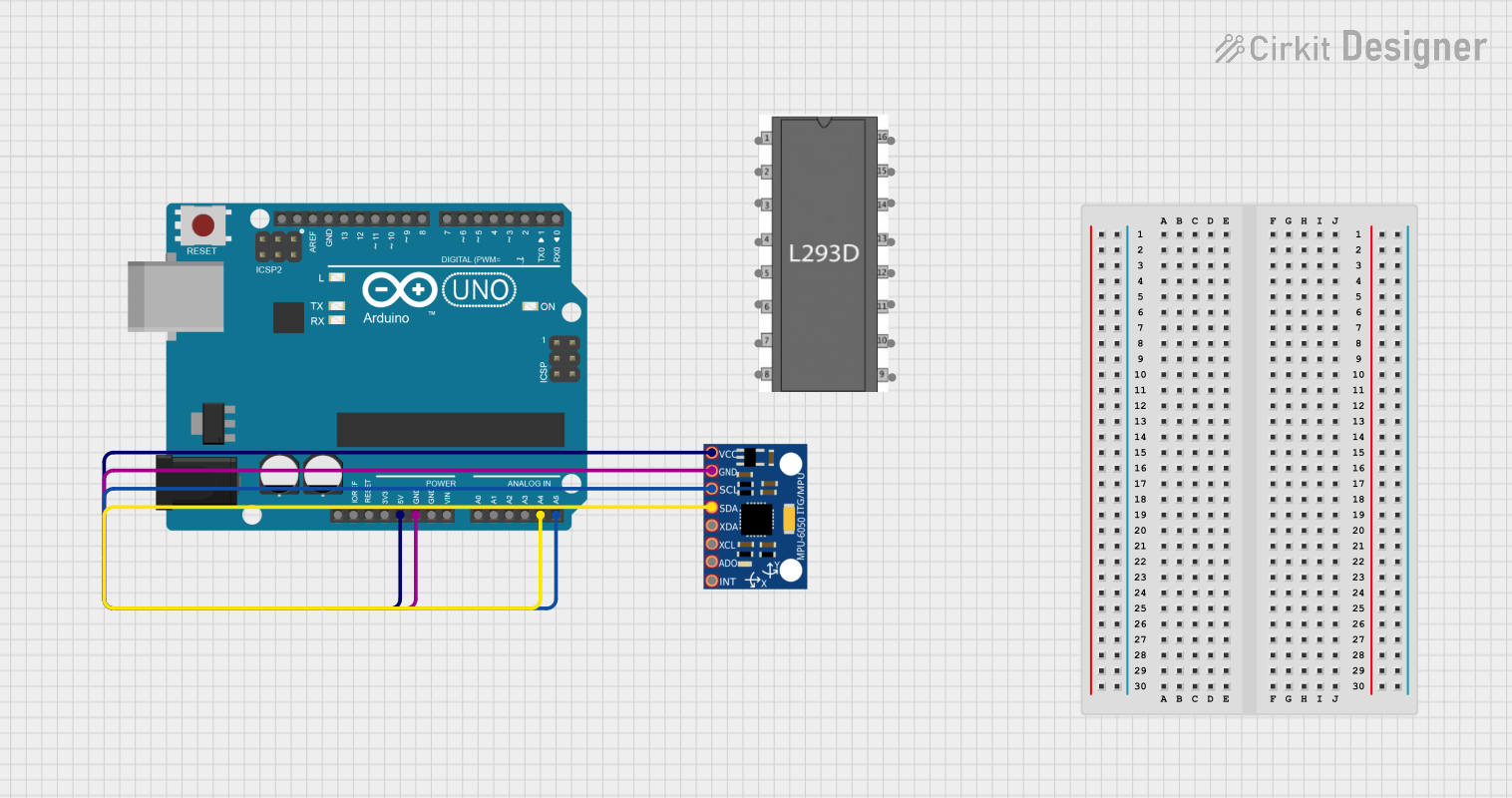
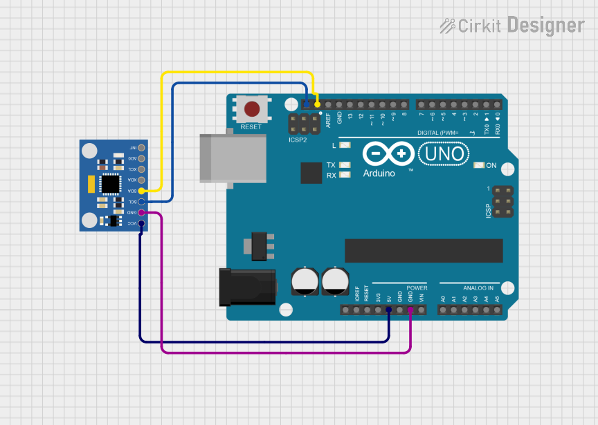
- Power Supply: Connect the VDD pin to a 3.3V power source and the GND pin to ground. If your microcontroller operates at 5V logic, use a level shifter for the I2C lines.
- I2C Communication: Connect the SCL and SDA pins to the corresponding I2C pins on your microcontroller. Use pull-up resistors (typically 4.7kΩ) on both lines.
- Address Selection: Use the AD0 pin to set the I2C address. Connect it to GND for the default address (0x68) or to VDD for an alternate address (0x69).
- Interrupt Pin: Optionally, connect the INT pin to a GPIO pin on your microcontroller to handle interrupts.
Best Practices:
- Use decoupling capacitors (e.g., 0.1µF) near the VDD pin to reduce noise.
- Avoid placing the sensor near high-frequency components to minimize interference.
- Calibrate the sensor before use to ensure accurate readings.
Example Code for Arduino UNO:
Below is an example of how to interface the MPU6050 Ankle with an Arduino UNO to read accelerometer and gyroscope data:
#include <Wire.h>

// MPU6050 I2C address (default is 0x68 when AD0 is connected to GND)
const int MPU6050_ADDR = 0x68;

// Registers for accelerometer and gyroscope data
const int ACCEL_XOUT_H = 0x3B;
const int GYRO_XOUT_H = 0x43;

void setup() {
  Wire.begin(); // Initialize I2C communication
  Serial.begin(9600); // Start serial communication for debugging

  // Wake up the MPU6050 (clear sleep mode bit)
  Wire.beginTransmission(MPU6050_ADDR);
  Wire.write(0x6B); // Power management register
  Wire.write(0);    // Set to 0 to wake up the sensor
  Wire.endTransmission();
}

void loop() {
  int16_t accelX, accelY, accelZ;
  int16_t gyroX, gyroY, gyroZ;

  // Read accelerometer data
  accelX = readMPU6050(ACCEL_XOUT_H);
  accelY = readMPU6050(ACCEL_XOUT_H + 2);
  accelZ = readMPU6050(ACCEL_XOUT_H + 4);

  // Read gyroscope data
  gyroX = readMPU6050(GYRO_XOUT_H);
  gyroY = readMPU6050(GYRO_XOUT_H + 2);
  gyroZ = readMPU6050(GYRO_XOUT_H + 4);

  // Print data to the Serial Monitor
  Serial.print("Accel: ");
  Serial.print(accelX); Serial.print(", ");
  Serial.print(accelY); Serial.print(", ");
  Serial.print(accelZ); Serial.print(" | ");

  Serial.print("Gyro: ");
  Serial.print(gyroX); Serial.print(", ");
  Serial.print(gyroY); Serial.print(", ");
  Serial.println(gyroZ);

  delay(500); // Delay for readability
}

// Function to read 16-bit data from MPU6050
int16_t readMPU6050(int reg) {
  Wire.beginTransmission(MPU6050_ADDR);
  Wire.write(reg); // Specify the register to read from
  Wire.endTransmission(false); // Restart I2C communication
  Wire.requestFrom(MPU6050_ADDR, 2); // Request 2 bytes of data

  // Combine high and low bytes
  int16_t data = Wire.read() << 8 | Wire.read();
  return data;
}
Troubleshooting and FAQs
Common Issues:
No Data from Sensor:
- Ensure the sensor is powered correctly (check VDD and GND connections).
- Verify the I2C pull-up resistors are in place.
- Check the I2C address (default is 0x68 unless AD0 is connected to VDD).
Inaccurate Readings:
- Perform sensor calibration to account for offsets.
- Ensure the sensor is mounted securely to avoid vibrations.
I2C Communication Errors:
- Check the SCL and SDA connections for continuity.
- Ensure the I2C clock speed does not exceed 400kHz.
FAQs:
Q: Can the MPU6050 Ankle be used with 5V microcontrollers?
A: Yes, but you must use a logic level shifter for the I2C lines to avoid damaging the sensor.
Q: How do I calibrate the MPU6050 Ankle?
A: Calibration involves reading raw data from the sensor while it is stationary and calculating offsets for each axis. These offsets can then be subtracted from subsequent readings.
Q: What is the maximum sampling rate of the MPU6050 Ankle?
A: The maximum sampling rate is 1kHz for both the accelerometer and gyroscope.
Q: Can I use the MPU6050 Ankle for step counting?
A: Yes, with appropriate algorithms, the accelerometer data can be used to detect steps and monitor gait.

 Open Project in Cirkit Designer