Cirkit Designer Logo
Cirkit Designer
Your all-in-one circuit design IDE
Home / 
Component Documentation

How to Use APC220: Examples, Pinouts, and Specs

Image of APC220
Cirkit Designer LogoDesign with APC220 in Cirkit Designer

Introduction

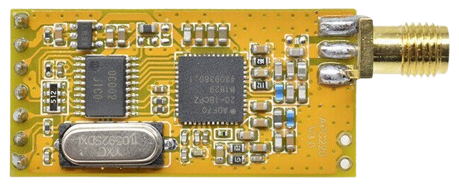
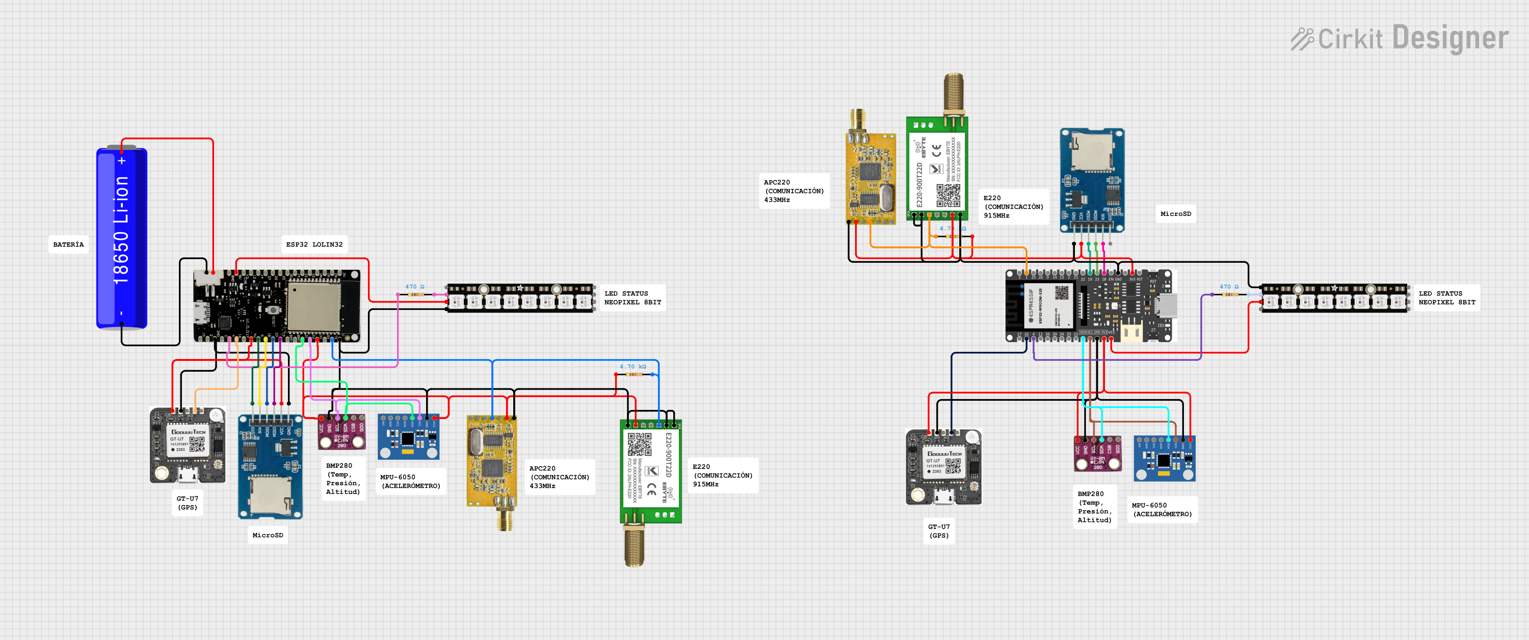
The APC220 radio communication module is a highly versatile and low-cost RF transceiver designed for embedding into a wide range of applications. It operates at 433MHz and is capable of transmitting data at distances of up to 1000 meters in open space. This makes it an ideal choice for hobbyist projects that require wireless communication, such as remote control systems, telemetry, and robotics.

Explore Projects Built with APC220

Use Cirkit Designer to design, explore, and prototype these projects online. Some projects support real-time simulation. Click "Open Project" to start designing instantly!
Arduino UNO and BMP085 Based Weather Station with Solar Charging and APC220 Wireless Communication
Image of Vicsat-1: A project utilizing APC220 in a practical application
This circuit features an Arduino UNO collecting environmental data from a BMP085 sensor and location data from a GPS module, transmitting it wirelessly via an APC220 module. It is powered by a solar-charged lithium-ion battery system, with a secondary Arduino UNO R4 WiFi and APC220 for potential expansion or separate functionality.
Cirkit Designer LogoOpen Project in Cirkit Designer
ESP32 Nano and APC220-Based Wireless Home Security System with RGB LED and Buzzer Alerts
Image of Alarm: A project utilizing APC220 in a practical application
This circuit is a home security system using an Arduino Nano ESP32, an APC220 wireless communication module, an RGB LED, a piezo buzzer, and a push switch. The system can arm and disarm itself, indicate status via the RGB LED, and alert with the buzzer and an email notification in case of an intruder alert.
Cirkit Designer LogoOpen Project in Cirkit Designer
Battery-Powered GPS Tracker with Bluetooth and APC220 Communication
Image of PANDURTKU0001_basic: A project utilizing APC220 in a practical application
This circuit integrates a SparkFun Qwiic GPS-RTK2 module with an APC220 radio module and an HC-05 Bluetooth module to provide GPS data transmission via both radio and Bluetooth. The circuit is powered by a 5V battery and includes switches to control power to the GPS module and the APC220 module, with an embedded GPS antenna for signal reception.
Cirkit Designer LogoOpen Project in Cirkit Designer
ESP32-Based GPS and Sensor Data Logger with LoRa and NeoPixel Display
Image of CANSAT Firebeetle 2: A project utilizing APC220 in a practical application
This circuit integrates an ESP32 microcontroller with various sensors and communication modules, including a GPS module, BMP280 sensor, MPU6050 accelerometer, and gyroscope, as well as LoRa and APC220 communication modules. It also includes a NeoPixel LED stick and a micro SD card module for data storage. The circuit is designed for data acquisition, processing, and wireless transmission, powered by a 18650 Li-ion battery.
Cirkit Designer LogoOpen Project in Cirkit Designer

Explore Projects Built with APC220

Use Cirkit Designer to design, explore, and prototype these projects online. Some projects support real-time simulation. Click "Open Project" to start designing instantly!
Image of Vicsat-1: A project utilizing APC220 in a practical application
Arduino UNO and BMP085 Based Weather Station with Solar Charging and APC220 Wireless Communication
This circuit features an Arduino UNO collecting environmental data from a BMP085 sensor and location data from a GPS module, transmitting it wirelessly via an APC220 module. It is powered by a solar-charged lithium-ion battery system, with a secondary Arduino UNO R4 WiFi and APC220 for potential expansion or separate functionality.
Cirkit Designer LogoOpen Project in Cirkit Designer
Image of Alarm: A project utilizing APC220 in a practical application
ESP32 Nano and APC220-Based Wireless Home Security System with RGB LED and Buzzer Alerts
This circuit is a home security system using an Arduino Nano ESP32, an APC220 wireless communication module, an RGB LED, a piezo buzzer, and a push switch. The system can arm and disarm itself, indicate status via the RGB LED, and alert with the buzzer and an email notification in case of an intruder alert.
Cirkit Designer LogoOpen Project in Cirkit Designer
Image of PANDURTKU0001_basic: A project utilizing APC220 in a practical application
Battery-Powered GPS Tracker with Bluetooth and APC220 Communication
This circuit integrates a SparkFun Qwiic GPS-RTK2 module with an APC220 radio module and an HC-05 Bluetooth module to provide GPS data transmission via both radio and Bluetooth. The circuit is powered by a 5V battery and includes switches to control power to the GPS module and the APC220 module, with an embedded GPS antenna for signal reception.
Cirkit Designer LogoOpen Project in Cirkit Designer
Image of CANSAT Firebeetle 2: A project utilizing APC220 in a practical application
ESP32-Based GPS and Sensor Data Logger with LoRa and NeoPixel Display
This circuit integrates an ESP32 microcontroller with various sensors and communication modules, including a GPS module, BMP280 sensor, MPU6050 accelerometer, and gyroscope, as well as LoRa and APC220 communication modules. It also includes a NeoPixel LED stick and a micro SD card module for data storage. The circuit is designed for data acquisition, processing, and wireless transmission, powered by a 18650 Li-ion battery.
Cirkit Designer LogoOpen Project in Cirkit Designer

Common Applications and Use Cases

  • Remote control vehicles and drones
  • Wireless sensor networks
  • Home automation systems
  • Telemetry for weather stations
  • Robotics communication
  • DIY electronics projects

Technical Specifications

Key Technical Details

  • Frequency: 433MHz
  • Modulation: GFSK
  • Power Output: 10mW-100mW (adjustable)
  • Communication Range: Up to 1000 meters (line-of-sight)
  • Serial Baud Rate: 1200bps to 115200bps (adjustable)
  • Interface: TTL/UART
  • Operating Voltage: 3.3V-5.5V
  • Operating Current: <35mA
  • Operating Temperature: -40°C to +85°C

Pin Configuration and Descriptions

Pin Number Name Description
1 VCC Power supply (3.3V-5.5V)
2 GND Ground connection
3 TXD Transmit data (TTL level)
4 RXD Receive data (TTL level)
5 SET Configuration mode (Low level: enter config mode)
6 AUX Status indicator (High: normal, Low: not working or in config mode)

Usage Instructions

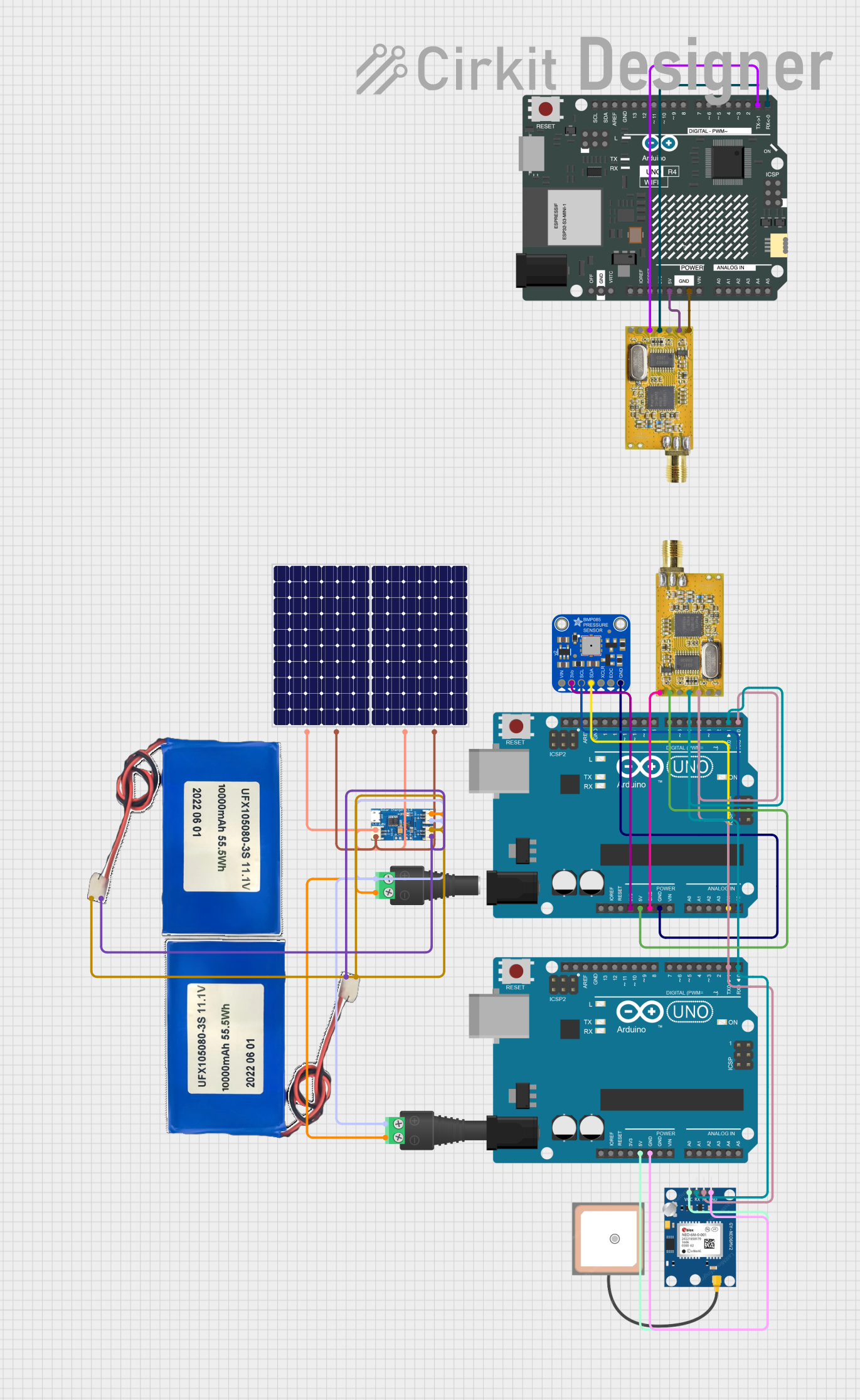
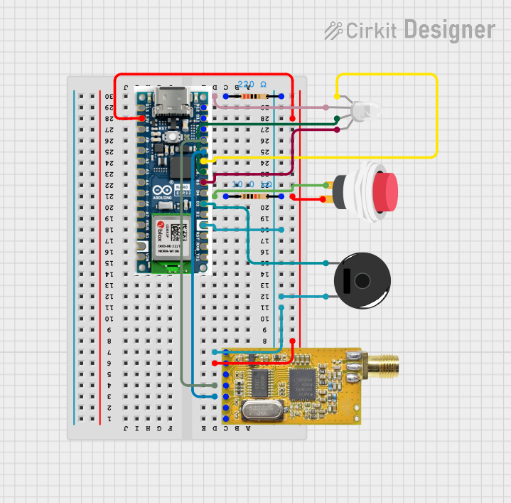
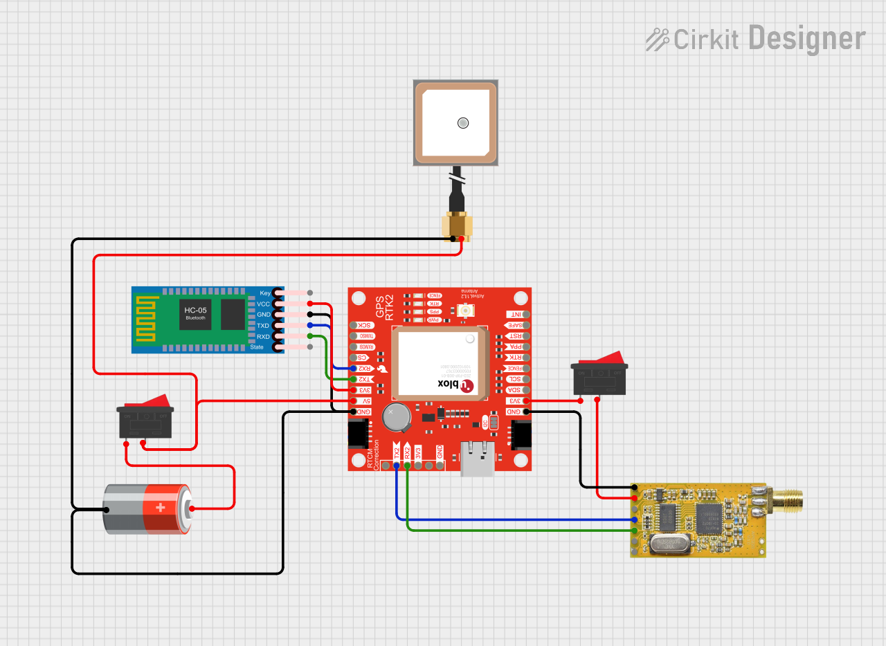
How to Use the Component in a Circuit

  1. Power Supply: Connect the VCC pin to a 3.3V-5.5V power source and the GND pin to the ground.
  2. Data Communication: Connect the TXD pin of one APC220 module to the RXD pin of the receiving device (e.g., Arduino) and vice versa for two-way communication.
  3. Configuration Mode: To enter configuration mode, pull the SET pin to a low level. This is typically done using a push button or by connecting it to a digital pin on a microcontroller.
  4. Status Indicator: The AUX pin can be connected to an LED or a digital input on a microcontroller to indicate the module's status.

Important Considerations and Best Practices

  • Ensure that the power supply is stable and within the specified voltage range.
  • Use a common ground for all devices in the communication network.
  • Avoid placing the module near metal objects or electronic devices that may cause interference.
  • Antenna selection and placement are crucial for optimal range and performance.
  • For reliable communication, configure both modules with the same baud rate and frequency settings.

Troubleshooting and FAQs

Common Issues Users Might Face

  • Communication Failure: Ensure that both modules are powered correctly and that the TXD and RXD pins are connected properly.
  • Short Range: Check the antenna connections and consider using a higher gain antenna for longer range.
  • Configuration Issues: Make sure the module is in configuration mode when changing settings, and that the settings match on both modules.

Solutions and Tips for Troubleshooting

  • Verify that the power supply is within the specified range and that all connections are secure.
  • Use the status indicator (AUX pin) to diagnose the module's state.
  • If range is an issue, experiment with different antenna types and orientations.
  • For configuration problems, consult the manufacturer's documentation for detailed instructions.

Example Code for Arduino UNO

#include <SoftwareSerial.h>

SoftwareSerial APC220(10, 11); // RX, TX

void setup() {
  // Start the APC220 communication
  APC220.begin(9600);
  Serial.begin(9600); // Start serial communication for debugging
}

void loop() {
  if (APC220.available()) { // Check if data is available to read
    Serial.write(APC220.read()); // Send the data to the Serial monitor
  }
  if (Serial.available()) { // Check if data is available to send
    APC220.write(Serial.read()); // Send data from Serial monitor to APC220
  }
}

Note: This example demonstrates basic serial communication between an Arduino UNO and the APC220 module. The SoftwareSerial library is used to create a serial connection on pins 10 and 11, which are connected to the APC220's RXD and TXD pins, respectively. Data received from the APC220 is sent to the Serial Monitor, and data entered into the Serial Monitor is sent to the APC220.

Remember to adjust the baud rate in the APC220.begin() function to match the configuration of your APC220 modules.