
How to Use LM2577 (TO220): Examples, Pinouts, and Specs
 Design with LM2577 (TO220) in Cirkit Designer
Introduction
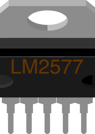
The LM2577T is a step-up (boost) voltage regulator manufactured by Texas Instruments. It is designed to convert a lower input voltage into a stable, higher output voltage, making it ideal for applications requiring efficient power conversion. With the ability to handle load currents up to 3A, the LM2577 is widely used in power supply circuits, battery-powered devices, and DC-DC converters. Its TO220 package ensures excellent thermal performance, making it suitable for high-power applications.
Explore Projects Built with LM2577 (TO220)
 Open Project in Cirkit Designer
 Open Project in Cirkit Designer
 Open Project in Cirkit Designer
 Open Project in Cirkit Designer
Explore Projects Built with LM2577 (TO220)
Open Project in Cirkit DesignerOpen Project in Cirkit DesignerOpen Project in Cirkit DesignerOpen Project in Cirkit DesignerCommon Applications
- DC-DC boost converters
- Battery-powered devices
- Solar power systems
- LED drivers
- Portable electronics
- Industrial power supplies
Technical Specifications
Key Technical Details
| Parameter | Value |
|---|---|
| Input Voltage Range | 3.5V to 40V |
| Output Voltage Range | Adjustable (up to 60V) |
| Maximum Output Current | 3A |
| Switching Frequency | 52 kHz (typical) |
| Efficiency | Up to 90% (depending on load and design) |
| Package Type | TO220 |
| Operating Temperature Range | -40°C to +125°C |
Pin Configuration and Descriptions
The LM2577T in the TO220 package has 5 pins. Below is the pinout and description:
| Pin Number | Pin Name | Description |
|---|---|---|
| 1 | VIN | Input voltage pin. Connect to the input power source (3.5V to 40V). |
| 2 | VSW | Switch output. Connect to the inductor and diode in the boost circuit. |
| 3 | GND | Ground pin. Connect to the circuit ground. |
| 4 | FB | Feedback pin. Used to set the output voltage via a resistor divider. |
| 5 | ON/OFF | Enable pin. Logic HIGH enables the regulator; logic LOW disables it. |
Usage Instructions
How to Use the LM2577 in a Circuit
The LM2577 is typically used in a boost converter circuit. Below is a step-by-step guide to using the component:
- Input Voltage: Connect the input voltage (3.5V to 40V) to the VIN pin. Ensure the input voltage is within the specified range.
- Inductor Selection: Choose an inductor with a suitable current rating (greater than 3A) and inductance value based on your desired output voltage and current.
- Diode Selection: Use a fast-recovery or Schottky diode with a voltage rating higher than the output voltage and a current rating of at least 3A.
- Output Voltage Setting: Use a resistor divider network connected to the FB pin to set the desired output voltage. The formula for the output voltage is: [ V_{OUT} = V_{REF} \times \left(1 + \frac{R1}{R2}\right) ] where ( V_{REF} ) is typically 1.23V.
- Capacitors: Add input and output capacitors to stabilize the circuit and reduce voltage ripple. Use low-ESR capacitors for better performance.
- Enable Pin: Connect the ON/OFF pin to logic HIGH (or leave it floating) to enable the regulator. Pull it LOW to disable the regulator.
Example Circuit
Below is a basic example of a boost converter circuit using the LM2577:
Input Voltage (VIN) --> [CIN] --> VIN (Pin 1)
                                |
                                |--> Inductor --> VSW (Pin 2) --> Diode --> Output Voltage (VOUT)
                                |
                               GND (Pin 3)
                                |
                                FB (Pin 4) <-- Resistor Divider <-- VOUT
                                |
                                ON/OFF (Pin 5) --> Logic HIGH/LOW
Arduino UNO Example Code
The LM2577 can be used with an Arduino UNO to control the enable pin. Below is an example code snippet:
// Define the pin connected to the LM2577 ON/OFF pin
const int enablePin = 7;

void setup() {
  // Set the enable pin as an output
  pinMode(enablePin, OUTPUT);

  // Enable the LM2577 by setting the pin HIGH
  digitalWrite(enablePin, HIGH);
}

void loop() {
  // Example: Toggle the LM2577 ON/OFF every 5 seconds
  digitalWrite(enablePin, LOW);  // Disable the LM2577
  delay(5000);                  // Wait for 5 seconds
  digitalWrite(enablePin, HIGH); // Enable the LM2577
  delay(5000);                  // Wait for 5 seconds
}
Important Notes:
- Ensure the input voltage is stable and within the specified range.
- Use proper heat dissipation techniques (e.g., heatsinks) for the TO220 package to prevent overheating.
- Verify the output voltage and current requirements before powering the load.
Troubleshooting and FAQs
Common Issues and Solutions
| Issue | Possible Cause | Solution |
|---|---|---|
| No output voltage | Input voltage is too low or disconnected | Check the input voltage and ensure it is within the 3.5V to 40V range. |
| Output voltage is unstable | Insufficient input/output capacitors | Add low-ESR capacitors to stabilize the circuit. |
| Overheating of the LM2577 | Excessive load current or poor heat dissipation | Reduce the load current or add a heatsink to the TO220 package. |
| Incorrect output voltage | Feedback resistor values are incorrect | Recalculate and adjust the resistor divider network. |
| Circuit not turning on/off | ON/OFF pin not properly connected | Ensure the ON/OFF pin is connected to the correct logic level. |
FAQs
Can the LM2577 be used for step-down (buck) conversion?
- No, the LM2577 is specifically designed for step-up (boost) conversion. For step-down applications, consider using a buck regulator like the LM2596.
What is the maximum output voltage of the LM2577?
- The LM2577 can output up to 60V, depending on the input voltage and circuit design.
How do I calculate the inductor value for my circuit?
- The inductor value depends on the input voltage, output voltage, switching frequency, and load current. Refer to the LM2577 datasheet for detailed design equations.
Can I leave the ON/OFF pin floating?
- Yes, the ON/OFF pin can be left floating, as it has an internal pull-up resistor. However, it is recommended to explicitly connect it to a logic level for better control.
What type of diode should I use with the LM2577?
- Use a fast-recovery or Schottky diode with a voltage rating higher than the output voltage and a current rating of at least 3A.
This concludes the documentation for the LM2577 (TO220). For further details, refer to the official datasheet provided by Texas Instruments.