How to Use Camera Shield: Examples, Pinouts, and Specs
Introduction
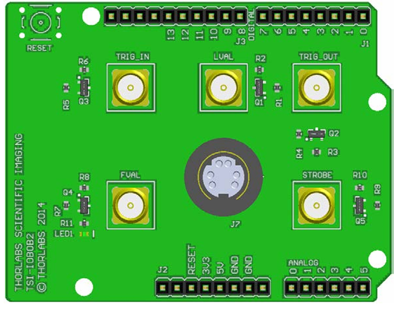
The Camera Shield (TSI-IOIBOB2), manufactured by Thor Labs, is a hardware module designed to interface cameras with microcontrollers or development boards. It enables seamless image capture and video streaming capabilities, making it an essential component for projects involving computer vision, robotics, surveillance, and IoT applications. The shield simplifies the integration of camera modules by providing the necessary hardware connections and communication protocols.
Explore Projects Built with Camera Shield
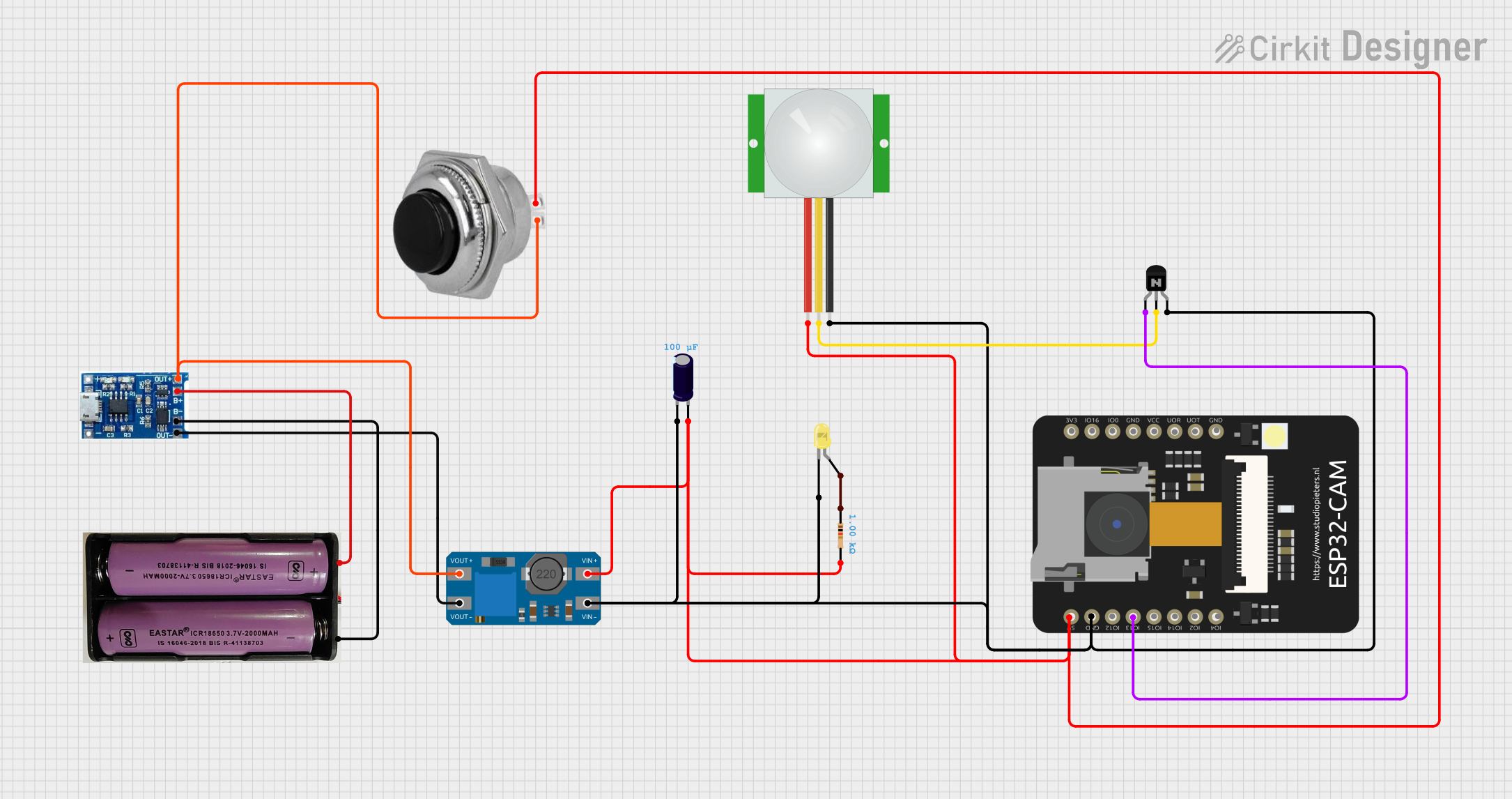
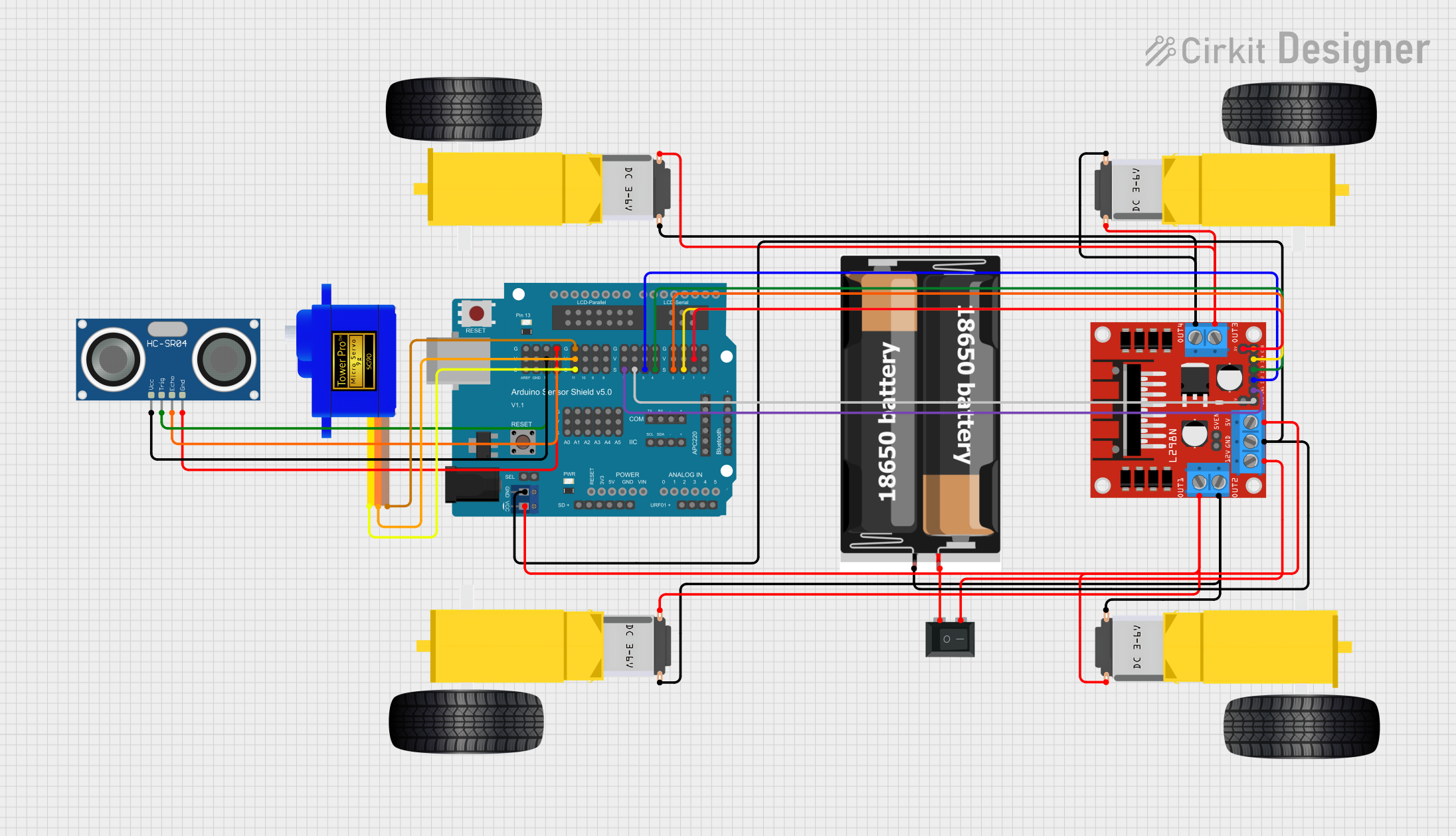
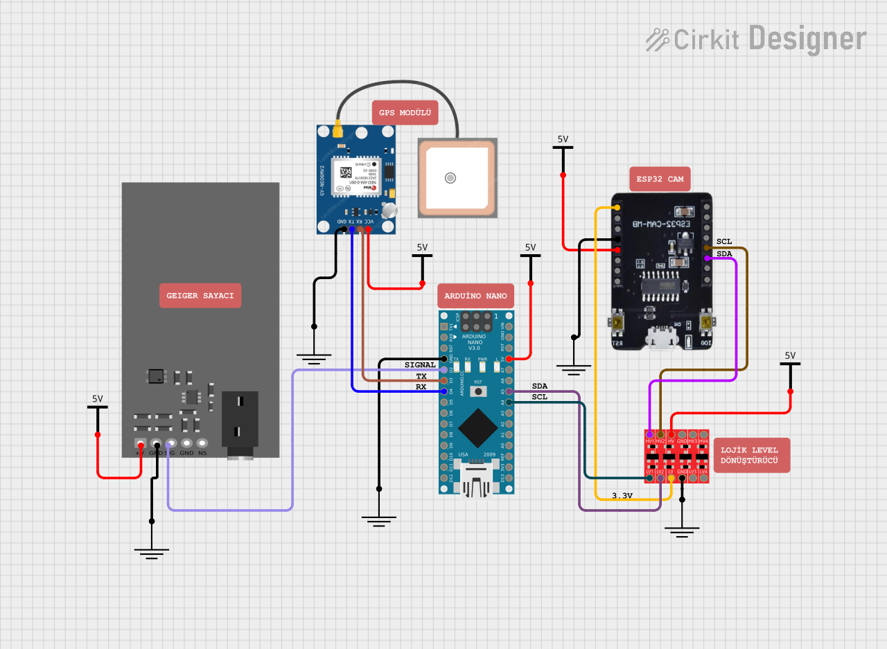
Explore Projects Built with Camera Shield
Common Applications and Use Cases
- Robotics: Vision-based navigation and object detection.
- IoT Devices: Smart home security systems and monitoring.
- Machine Learning: Image data collection for AI model training.
- Surveillance: Real-time video streaming and recording.
- Prototyping: Rapid development of camera-based projects.
Technical Specifications
The following table outlines the key technical details of the Camera Shield (TSI-IOIBOB2):
| Specification | Details |
|---|---|
| Manufacturer | Thor Labs |
| Part ID | TSI-IOIBOB2 |
| Input Voltage | 3.3V to 5V |
| Communication Interface | I2C, SPI, UART |
| Camera Interface | 8-bit parallel, MIPI CSI-2 |
| Maximum Resolution | Up to 1080p |
| Frame Rate | Up to 60 FPS (depending on camera module) |
| Operating Temperature | -20°C to 70°C |
| Dimensions | 50mm x 50mm |
Pin Configuration and Descriptions
The Camera Shield features a standard pinout for easy integration with microcontrollers. Below is the pin configuration:
| Pin | Name | Description |
|---|---|---|
| 1 | GND | Ground connection |
| 2 | VCC | Power supply (3.3V or 5V) |
| 3 | SDA | I2C Data Line |
| 4 | SCL | I2C Clock Line |
| 5 | MISO | SPI Master In Slave Out |
| 6 | MOSI | SPI Master Out Slave In |
| 7 | SCK | SPI Clock |
| 8 | CS | SPI Chip Select |
| 9 | TX | UART Transmit |
| 10 | RX | UART Receive |
| 11 | D0-D7 | 8-bit Parallel Data Lines |
| 12 | RESET | Reset pin for the camera module |
| 13 | PCLK | Pixel Clock for parallel interface |
| 14 | HSYNC | Horizontal Sync signal |
| 15 | VSYNC | Vertical Sync signal |
Usage Instructions
How to Use the Camera Shield in a Circuit
- Power the Shield: Connect the VCC and GND pins to the appropriate power supply (3.3V or 5V).
- Connect Communication Lines: Depending on your microcontroller, connect the I2C, SPI, or UART pins to the corresponding pins on the microcontroller.
- Attach a Camera Module: Plug in a compatible camera module to the shield's camera interface.
- Initialize Communication: Use the microcontroller's software to initialize communication with the shield and configure the camera settings.
- Capture Images or Stream Video: Use the provided APIs or libraries to capture images or stream video data.
Important Considerations and Best Practices
- Power Supply: Ensure the power supply matches the voltage requirements of both the shield and the camera module.
- Signal Integrity: Use short and shielded cables for high-speed signals to minimize noise.
- Camera Compatibility: Verify that the camera module is compatible with the shield's interface (e.g., MIPI CSI-2 or parallel).
- Heat Management: If operating at high frame rates or resolutions, ensure proper ventilation to prevent overheating.
- Software Libraries: Use the manufacturer's recommended libraries or drivers for optimal performance.
Example Code for Arduino UNO
Below is an example of how to interface the Camera Shield with an Arduino UNO using the I2C protocol:
#include <Wire.h> // Include the Wire library for I2C communication

#define CAMERA_I2C_ADDRESS 0x42 // Replace with the actual I2C address of the camera

void setup() {
  Wire.begin(); // Initialize I2C communication
  Serial.begin(9600); // Start serial communication for debugging

  // Initialize the camera
  Wire.beginTransmission(CAMERA_I2C_ADDRESS);
  Wire.write(0x01); // Example command to initialize the camera
  if (Wire.endTransmission() == 0) {
    Serial.println("Camera initialized successfully!");
  } else {
    Serial.println("Failed to initialize the camera.");
  }
}

void loop() {
  // Example: Capture an image
  Wire.beginTransmission(CAMERA_I2C_ADDRESS);
  Wire.write(0x02); // Example command to capture an image
  if (Wire.endTransmission() == 0) {
    Serial.println("Image captured successfully!");
  } else {
    Serial.println("Failed to capture image.");
  }

  delay(1000); // Wait for 1 second before capturing the next image
}
Troubleshooting and FAQs
Common Issues and Solutions
Camera Not Detected:
- Cause: Incorrect wiring or incompatible camera module.
- Solution: Double-check the connections and ensure the camera module is compatible with the shield.
No Image or Video Output:
- Cause: Incorrect initialization or communication failure.
- Solution: Verify the initialization code and ensure the communication protocol is correctly configured.
Overheating:
- Cause: Prolonged operation at high frame rates or resolutions.
- Solution: Add a heat sink or improve ventilation around the shield.
Distorted Images:
- Cause: Signal noise or improper camera settings.
- Solution: Use shielded cables and adjust the camera settings via software.
FAQs
Q: Can I use this shield with Raspberry Pi?
- A: Yes, the shield is compatible with Raspberry Pi via the I2C, SPI, or UART interfaces.
Q: What is the maximum supported resolution?
- A: The shield supports resolutions up to 1080p, depending on the camera module.
Q: Does the shield come with a camera module?
- A: No, the camera module must be purchased separately.
Q: Can I use multiple shields with one microcontroller?
- A: Yes, but ensure the microcontroller has enough resources and unique addresses for each shield.
This documentation provides a comprehensive guide to using the Camera Shield (TSI-IOIBOB2) effectively. For further assistance, refer to the manufacturer's datasheet or support resources.