How to Use oximeter: Examples, Pinouts, and Specs
Introduction
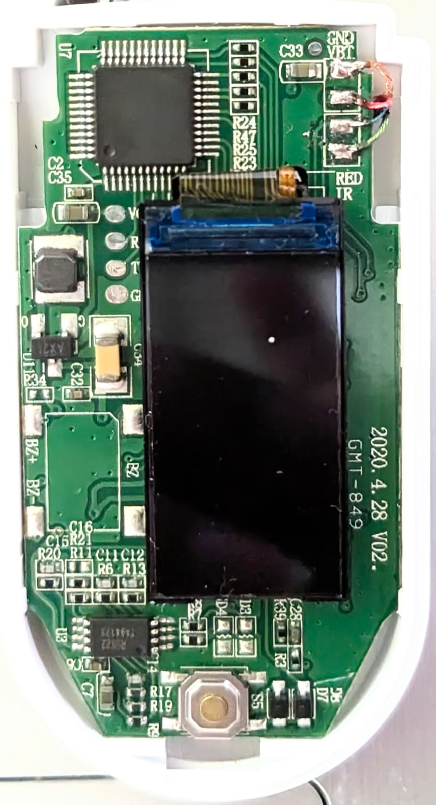
An oximeter is a device used to measure the oxygen saturation level in the blood, typically by attaching to a fingertip. It is a non-invasive tool that provides critical information about a person's respiratory function. Oximeters are commonly used in medical settings, fitness monitoring, and home health care to ensure that individuals maintain healthy oxygen levels.
Explore Projects Built with oximeter
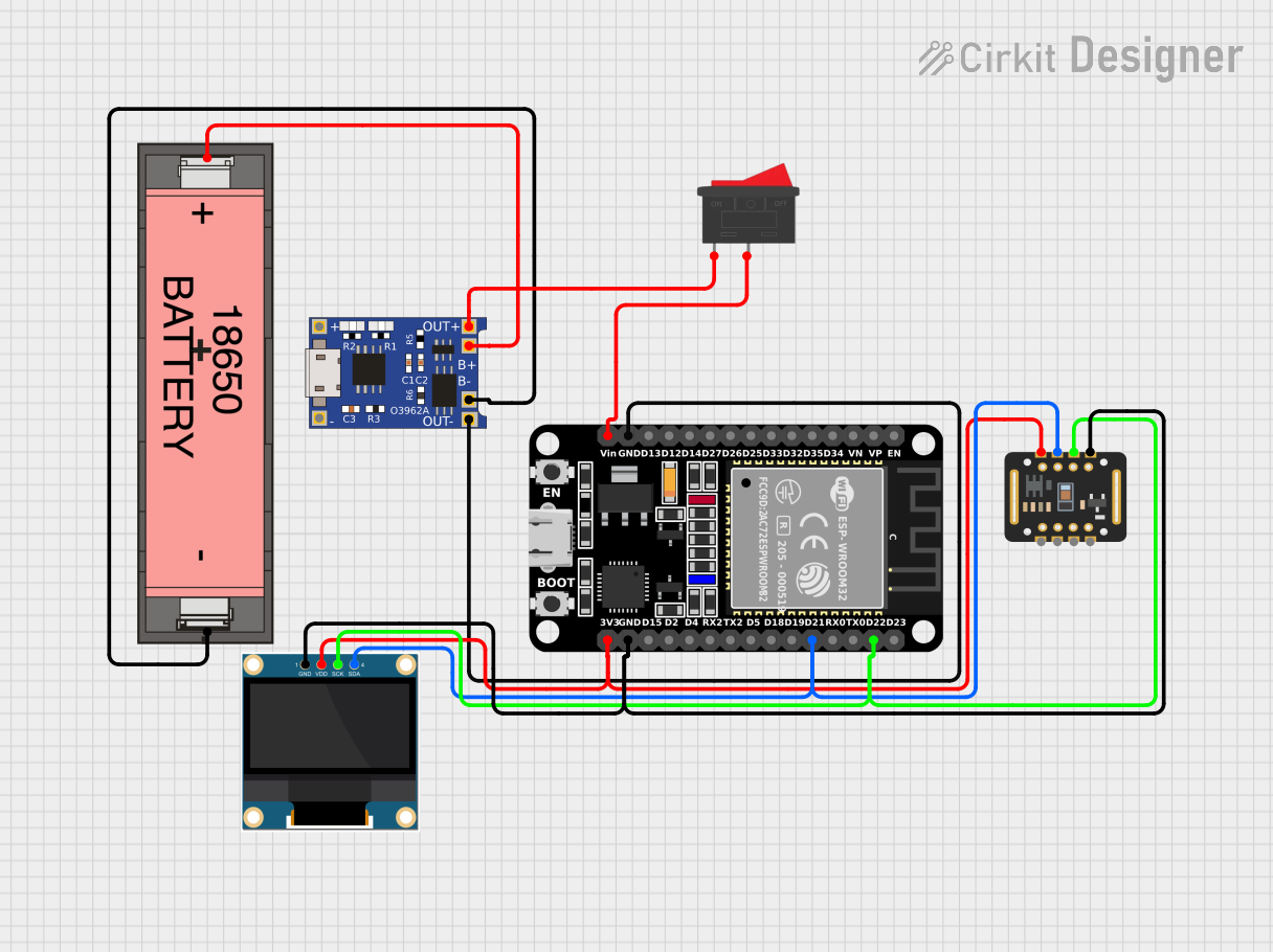

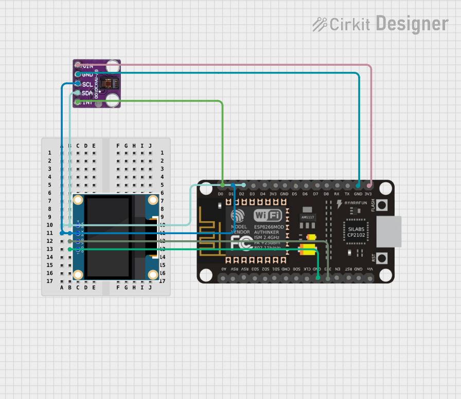
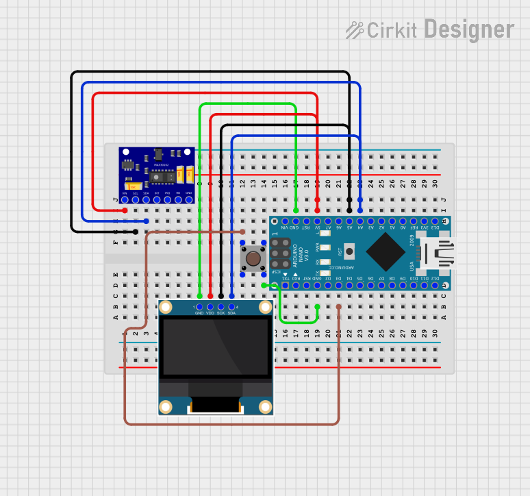
Explore Projects Built with oximeter
Technical Specifications
Key Technical Details
| Parameter | Value |
|---|---|
| Operating Voltage | 3.3V - 5V |
| Operating Current | 20mA - 30mA |
| Measurement Range | 0% - 100% SpO2 |
| Accuracy | ±2% (70% - 100% SpO2 range) |
| Display Type | LED or OLED |
| Communication | I2C or UART |
| Sensor Type | Photoplethysmography (PPG) |
Pin Configuration and Descriptions
I2C Interface
| Pin Number | Pin Name | Description |
|---|---|---|
| 1 | VCC | Power supply (3.3V - 5V) |
| 2 | GND | Ground |
| 3 | SDA | Serial Data Line (I2C) |
| 4 | SCL | Serial Clock Line (I2C) |
UART Interface
| Pin Number | Pin Name | Description |
|---|---|---|
| 1 | VCC | Power supply (3.3V - 5V) |
| 2 | GND | Ground |
| 3 | TX | Transmit Data (UART) |
| 4 | RX | Receive Data (UART) |
Usage Instructions
How to Use the Oximeter in a Circuit
- Power Supply: Connect the VCC pin to a 3.3V or 5V power supply and the GND pin to the ground.
- Communication Interface: Depending on the interface (I2C or UART), connect the corresponding pins:
- For I2C: Connect the SDA and SCL pins to the respective pins on the microcontroller.
- For UART: Connect the TX and RX pins to the respective pins on the microcontroller.
- Sensor Placement: Attach the oximeter sensor to the fingertip or earlobe for accurate readings.
- Initialization: Initialize the communication protocol in your microcontroller code.
- Reading Data: Continuously read the data from the oximeter and process it to obtain the SpO2 levels.
Important Considerations and Best Practices
- Stable Power Supply: Ensure a stable power supply to avoid fluctuations in readings.
- Proper Placement: Place the sensor correctly on the fingertip or earlobe for accurate measurements.
- Ambient Light: Minimize ambient light interference by covering the sensor if necessary.
- Calibration: Periodically calibrate the oximeter to maintain accuracy.
- Code Implementation: Use appropriate libraries and functions to handle the communication and data processing.
Example Code for Arduino UNO (I2C Interface)
#include <Wire.h>
#include "OximeterLibrary.h" // Replace with the actual library name

Oximeter oximeter;

void setup() {
  Serial.begin(9600);
  Wire.begin();
  oximeter.begin();
}

void loop() {
  if (oximeter.read()) {
    Serial.print("SpO2: ");
    Serial.print(oximeter.getSpO2());
    Serial.print("%, Heart Rate: ");
    Serial.print(oximeter.getHeartRate());
    Serial.println(" bpm");
  } else {
    Serial.println("Failed to read from oximeter");
  }
  delay(1000); // Wait for 1 second before the next reading
}
Troubleshooting and FAQs
Common Issues and Solutions
No Readings or Erratic Readings
- Solution: Ensure the sensor is properly attached to the fingertip or earlobe. Check the power supply and connections.
Inaccurate Readings
- Solution: Minimize ambient light interference and ensure the sensor is placed correctly. Calibrate the oximeter if necessary.
Communication Errors
- Solution: Verify the I2C or UART connections and ensure the correct initialization in the code.
FAQs
Q1: Can I use the oximeter with a 3.3V power supply?
- A1: Yes, the oximeter can operate with a 3.3V or 5V power supply.
Q2: How often should I calibrate the oximeter?
- A2: Calibration frequency depends on usage. For regular use, calibrate monthly or as recommended by the manufacturer.
Q3: Can the oximeter be used on other body parts?
- A3: While the fingertip and earlobe are common, other body parts may not provide accurate readings.
Q4: What should I do if the oximeter is not responding?
- A4: Check all connections, ensure the power supply is stable, and verify the code for any errors.
By following this documentation, users can effectively utilize the oximeter for accurate and reliable oxygen saturation measurements.