Cirkit Designer Logo
Cirkit Designer
Your all-in-one circuit design IDE
Home / 
Component Documentation

How to Use TSAL6200: Examples, Pinouts, and Specs

Image of TSAL6200
Cirkit Designer LogoDesign with TSAL6200 in Cirkit Designer

Introduction

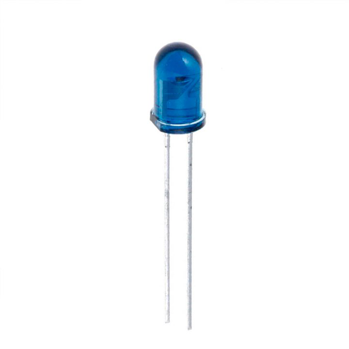
The TSAL6200 is an infrared (IR) emitting diode designed for remote control applications. It emits infrared light at a wavelength of 940 nm, making it ideal for use in various remote control systems, including television remotes, air conditioning units, and other consumer electronics. The TSAL6200 is known for its high radiant intensity and fast switching times, ensuring reliable performance in demanding applications.

Explore Projects Built with TSAL6200

Use Cirkit Designer to design, explore, and prototype these projects online. Some projects support real-time simulation. Click "Open Project" to start designing instantly!
Bluetooth-Enabled Audio Amplifier System with Subwoofer and Cooling Fan
Image of 2.1 120w amplifier: A project utilizing TSAL6200 in a practical application
This circuit is a Bluetooth-enabled audio amplifier system with a subwoofer pre-amp and dual 8-ohm speakers. It includes a 12V power supply, a 7805 voltage regulator, and a cooling fan, with a toggle switch to control power. The Bluetooth module provides audio input to the amplifiers, which drive the speakers and subwoofer.
Cirkit Designer LogoOpen Project in Cirkit Designer
LD1117 Voltage Regulator Circuit with Input and Output Capacitors
Image of regulator: A project utilizing TSAL6200 in a practical application
This circuit is designed to provide a stable output voltage from an input voltage source. It uses an LD1117 voltage regulator in conjunction with an electrolytic capacitor on the input side and a tantalum capacitor on the output side to filter noise and stabilize the voltage. The common ground ensures a reference point for all components.
Cirkit Designer LogoOpen Project in Cirkit Designer
ESP32-Powered Wi-Fi Controlled Robotic Car with OLED Display and Ultrasonic Sensor
Image of playbot: A project utilizing TSAL6200 in a practical application
This circuit is a battery-powered system featuring an ESP32 microcontroller that controls an OLED display, a motor driver for two hobby motors, an ultrasonic sensor for distance measurement, and a DFPlayer Mini for audio output through a loudspeaker. The TP4056 module manages battery charging, and a step-up boost converter provides a stable 5V supply to the components.
Cirkit Designer LogoOpen Project in Cirkit Designer
Solar-Powered Environmental Monitoring System with ESP32 and Cellular Connectivity
Image of IoT Ola: A project utilizing TSAL6200 in a practical application
This circuit features an ESP32 microcontroller interfaced with a BME/BMP280 sensor for environmental data and an MH-Z19B sensor for CO2 measurement, both communicating via I2C (SCL, SDA) and serial (TX, RX) connections respectively. It includes a TP4056 module for charging an 18650 Li-ion battery from a solar panel, with a step-up boost converter to provide stable voltage to the MH-Z19B sensor and a voltage regulator for the SIM800L GSM module. The capacitors are likely used for power supply filtering or decoupling.
Cirkit Designer LogoOpen Project in Cirkit Designer

Explore Projects Built with TSAL6200

Use Cirkit Designer to design, explore, and prototype these projects online. Some projects support real-time simulation. Click "Open Project" to start designing instantly!
Image of 2.1 120w amplifier: A project utilizing TSAL6200 in a practical application
Bluetooth-Enabled Audio Amplifier System with Subwoofer and Cooling Fan
This circuit is a Bluetooth-enabled audio amplifier system with a subwoofer pre-amp and dual 8-ohm speakers. It includes a 12V power supply, a 7805 voltage regulator, and a cooling fan, with a toggle switch to control power. The Bluetooth module provides audio input to the amplifiers, which drive the speakers and subwoofer.
Cirkit Designer LogoOpen Project in Cirkit Designer
Image of regulator: A project utilizing TSAL6200 in a practical application
LD1117 Voltage Regulator Circuit with Input and Output Capacitors
This circuit is designed to provide a stable output voltage from an input voltage source. It uses an LD1117 voltage regulator in conjunction with an electrolytic capacitor on the input side and a tantalum capacitor on the output side to filter noise and stabilize the voltage. The common ground ensures a reference point for all components.
Cirkit Designer LogoOpen Project in Cirkit Designer
Image of playbot: A project utilizing TSAL6200 in a practical application
ESP32-Powered Wi-Fi Controlled Robotic Car with OLED Display and Ultrasonic Sensor
This circuit is a battery-powered system featuring an ESP32 microcontroller that controls an OLED display, a motor driver for two hobby motors, an ultrasonic sensor for distance measurement, and a DFPlayer Mini for audio output through a loudspeaker. The TP4056 module manages battery charging, and a step-up boost converter provides a stable 5V supply to the components.
Cirkit Designer LogoOpen Project in Cirkit Designer
Image of IoT Ola: A project utilizing TSAL6200 in a practical application
Solar-Powered Environmental Monitoring System with ESP32 and Cellular Connectivity
This circuit features an ESP32 microcontroller interfaced with a BME/BMP280 sensor for environmental data and an MH-Z19B sensor for CO2 measurement, both communicating via I2C (SCL, SDA) and serial (TX, RX) connections respectively. It includes a TP4056 module for charging an 18650 Li-ion battery from a solar panel, with a step-up boost converter to provide stable voltage to the MH-Z19B sensor and a voltage regulator for the SIM800L GSM module. The capacitors are likely used for power supply filtering or decoupling.
Cirkit Designer LogoOpen Project in Cirkit Designer

Technical Specifications

Key Technical Details

Parameter Value
Peak Wavelength 940 nm
Radiant Intensity 70 mW/sr (typical)
Forward Voltage 1.35 V (typical)
Forward Current 100 mA (maximum)
Reverse Voltage 5 V (maximum)
Power Dissipation 200 mW (maximum)
Rise Time 15 ns
Fall Time 15 ns
Package Type Leaded
Viewing Angle ±10°

Pin Configuration and Descriptions

Pin Number Pin Name Description
1 Anode Positive terminal
2 Cathode Negative terminal

Usage Instructions

How to Use the TSAL6200 in a Circuit

To use the TSAL6200 in a circuit, follow these steps:

  1. Connect the Anode (Pin 1) to a current-limiting resistor: This resistor is necessary to prevent excessive current from damaging the diode. The value of the resistor can be calculated using Ohm's Law: ( R = \frac{V_{supply} - V_{forward}}{I_{forward}} ).

  2. Connect the Cathode (Pin 2) to ground: This completes the circuit and allows current to flow through the diode when the circuit is powered.

  3. Power the circuit: Apply the appropriate voltage to the circuit, ensuring that the forward current does not exceed the maximum rating of 100 mA.

Important Considerations and Best Practices

  • Current Limiting: Always use a current-limiting resistor to protect the diode from excessive current.
  • Heat Dissipation: Ensure adequate heat dissipation to prevent overheating, especially in high-power applications.
  • Polarity: Observe correct polarity when connecting the diode to avoid damage.
  • Switching Speed: Take advantage of the fast switching times (15 ns rise and fall times) for high-speed applications.

Example Circuit with Arduino UNO

Here is an example of how to connect the TSAL6200 to an Arduino UNO for a simple IR remote control application:

Circuit Diagram

Arduino UNO          TSAL6200
-----------          -------
  5V  -------------| Anode (Pin 1)
  GND -------------| Cathode (Pin 2)
  D3  -------------| Resistor (220Ω) -> Anode (Pin 1)

Arduino Code

// Define the pin connected to the TSAL6200
const int irLedPin = 3;

void setup() {
  // Set the IR LED pin as an output
  pinMode(irLedPin, OUTPUT);
}

void loop() {
  // Turn the IR LED on
  digitalWrite(irLedPin, HIGH);
  delay(1000); // Keep it on for 1 second

  // Turn the IR LED off
  digitalWrite(irLedPin, LOW);
  delay(1000); // Keep it off for 1 second
}

Troubleshooting and FAQs

Common Issues

  1. IR LED Not Emitting Light:

    • Solution: Ensure the correct polarity is observed. Check the connections and verify that the current-limiting resistor is of the correct value.
  2. Overheating:

    • Solution: Ensure that the forward current does not exceed 100 mA. Use appropriate heat dissipation methods.
  3. Inconsistent Performance:

    • Solution: Verify that the power supply is stable and within the specified voltage range. Check for loose connections.

FAQs

Q1: Can I use the TSAL6200 without a current-limiting resistor?

  • A1: No, using the TSAL6200 without a current-limiting resistor can result in excessive current flow, potentially damaging the diode.

Q2: What is the maximum distance the TSAL6200 can cover?

  • A2: The maximum distance depends on the receiver's sensitivity and the environment. Typically, it can cover several meters in a clear line of sight.

Q3: Can I use the TSAL6200 for data transmission?

  • A3: Yes, the TSAL6200's fast switching times make it suitable for data transmission applications.

By following this documentation, users can effectively integrate the TSAL6200 into their remote control and IR communication projects, ensuring reliable and efficient performance.