Cirkit Designer Logo
Cirkit Designer
Your all-in-one circuit design IDE
Home / 
Component Documentation

How to Use Current Sensor: Examples, Pinouts, and Specs

Image of Current Sensor
Cirkit Designer LogoDesign with Current Sensor in Cirkit Designer

Introduction

A current sensor is a device that measures the flow of electric current in a circuit, typically providing an output signal proportional to the current level. These sensors are widely used in various applications, including power monitoring, motor control, battery management systems, and renewable energy systems. Current sensors are essential for ensuring the safe and efficient operation of electrical and electronic systems.

Common applications and use cases:

  • Monitoring current in power supply circuits
  • Overcurrent protection in electrical systems
  • Measuring current in motor drives and inverters
  • Battery charge and discharge monitoring
  • Energy metering in renewable energy systems (e.g., solar panels)

Explore Projects Built with Current Sensor

Use Cirkit Designer to design, explore, and prototype these projects online. Some projects support real-time simulation. Click "Open Project" to start designing instantly!
Wemos S2 Mini Controlled Smart Device with OLED Display, Thermal Printing, and RGB LED Strip
Image of DT NEA - Noah Patel: A project utilizing Current Sensor in a practical application
This circuit features a Wemos S2 Mini microcontroller that controls a WS2812 RGB LED strip and communicates with a 0.96" OLED display and a 58mm mini thermal printer. The ACS712 Current Sensor is interfaced with the microcontroller to monitor current, and power is managed by a CD42 BMS connected to two 18650 Li-ion batteries, with a USB-C PD Trigger Board for power delivery. The circuit is designed for visual output (LED strip, OLED display), printing capabilities, and current sensing, likely for a portable, battery-powered monitoring and display device.
Cirkit Designer LogoOpen Project in Cirkit Designer
ESP32-Based Current Monitoring and Temperature Sensing System
Image of SISTEMA DE MONITOREO: A project utilizing Current Sensor in a practical application
This circuit is designed to measure current using an ACS712 Current Sensor and temperature using a DS18B20 sensor, with an ESP32 microcontroller to process and possibly communicate the sensor data. The ACS712 sensor output is connected to one of the ESP32's analog input pins (D34), while the DS18B20's signal line is interfaced with a digital input pin (D23) through a pull-up resistor (4.7k Ohms). The ESP32 is powered through its Vin pin, and both sensors share a common ground with the ESP32.
Cirkit Designer LogoOpen Project in Cirkit Designer
Arduino UNO Based Ammeter with LCD Display
Image of ammeter: A project utilizing Current Sensor in a practical application
This circuit features an Arduino UNO microcontroller interfaced with an ACS712 current sensor and a 16x2 LCD screen using I2C communication. The Arduino reads the current value from the sensor and displays it on the LCD screen, also sending the data to the serial monitor. It is designed to function as an ammeter, measuring and displaying the current flowing through the sensor.
Cirkit Designer LogoOpen Project in Cirkit Designer
Arduino UNO-Based Weather Station with LCD Display and Motor Control
Image of final year project: A project utilizing Current Sensor in a practical application
This circuit is a multi-sensor monitoring system controlled by an Arduino UNO, which reads data from a temperature sensor, current sensor, wind vane, and BMP280 pressure sensor. It also controls a brushless motor and displays the collected data on an LCD screen. The system includes a load cell interface for force measurement and uses a potentiometer for motor speed control.
Cirkit Designer LogoOpen Project in Cirkit Designer

Explore Projects Built with Current Sensor

Use Cirkit Designer to design, explore, and prototype these projects online. Some projects support real-time simulation. Click "Open Project" to start designing instantly!
Image of DT NEA - Noah Patel: A project utilizing Current Sensor in a practical application
Wemos S2 Mini Controlled Smart Device with OLED Display, Thermal Printing, and RGB LED Strip
This circuit features a Wemos S2 Mini microcontroller that controls a WS2812 RGB LED strip and communicates with a 0.96" OLED display and a 58mm mini thermal printer. The ACS712 Current Sensor is interfaced with the microcontroller to monitor current, and power is managed by a CD42 BMS connected to two 18650 Li-ion batteries, with a USB-C PD Trigger Board for power delivery. The circuit is designed for visual output (LED strip, OLED display), printing capabilities, and current sensing, likely for a portable, battery-powered monitoring and display device.
Cirkit Designer LogoOpen Project in Cirkit Designer
Image of SISTEMA DE MONITOREO: A project utilizing Current Sensor in a practical application
ESP32-Based Current Monitoring and Temperature Sensing System
This circuit is designed to measure current using an ACS712 Current Sensor and temperature using a DS18B20 sensor, with an ESP32 microcontroller to process and possibly communicate the sensor data. The ACS712 sensor output is connected to one of the ESP32's analog input pins (D34), while the DS18B20's signal line is interfaced with a digital input pin (D23) through a pull-up resistor (4.7k Ohms). The ESP32 is powered through its Vin pin, and both sensors share a common ground with the ESP32.
Cirkit Designer LogoOpen Project in Cirkit Designer
Image of ammeter: A project utilizing Current Sensor in a practical application
Arduino UNO Based Ammeter with LCD Display
This circuit features an Arduino UNO microcontroller interfaced with an ACS712 current sensor and a 16x2 LCD screen using I2C communication. The Arduino reads the current value from the sensor and displays it on the LCD screen, also sending the data to the serial monitor. It is designed to function as an ammeter, measuring and displaying the current flowing through the sensor.
Cirkit Designer LogoOpen Project in Cirkit Designer
Image of final year project: A project utilizing Current Sensor in a practical application
Arduino UNO-Based Weather Station with LCD Display and Motor Control
This circuit is a multi-sensor monitoring system controlled by an Arduino UNO, which reads data from a temperature sensor, current sensor, wind vane, and BMP280 pressure sensor. It also controls a brushless motor and displays the collected data on an LCD screen. The system includes a load cell interface for force measurement and uses a potentiometer for motor speed control.
Cirkit Designer LogoOpen Project in Cirkit Designer

Technical Specifications

The technical specifications of a current sensor can vary depending on the specific model and type. Below is an example of a typical Hall-effect-based current sensor:

Parameter Value
Measurement Range ±30 A
Supply Voltage (Vcc) 5 V DC
Output Voltage Range 0.5 V to 4.5 V
Sensitivity 66 mV/A
Accuracy ±1% of full-scale reading
Response Time < 5 µs
Operating Temperature -40°C to +85°C
Isolation Voltage 2.1 kV RMS

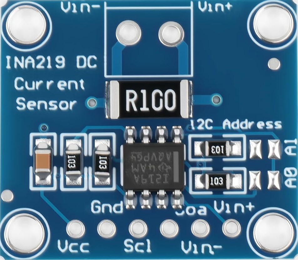
Pin Configuration and Descriptions

Below is the pin configuration for a typical 5-pin current sensor module:

Pin Name Description
1 Vcc Power supply input (typically 5 V DC)
2 GND Ground connection
3 Vout Analog output voltage proportional to the current
4 NC (Not Connected) No connection (reserved for future use)
5 Filter Optional pin for connecting a capacitor to filter noise

Usage Instructions

How to Use the Component in a Circuit

  1. Power the Sensor: Connect the Vcc pin to a 5 V DC power supply and the GND pin to the ground of your circuit.
  2. Connect the Load: Pass the wire carrying the current to be measured through the sensor's sensing region (e.g., a Hall-effect sensor loop or shunt resistor).
  3. Read the Output: Connect the Vout pin to an analog input pin of a microcontroller or an ADC (Analog-to-Digital Converter) to read the voltage proportional to the current.
  4. Optional Filtering: If noise is present in the output signal, connect a capacitor (e.g., 0.1 µF) between the Filter pin and GND to smooth the signal.

Important Considerations and Best Practices

  • Ensure the current being measured does not exceed the sensor's maximum rating to avoid damage.
  • Use proper isolation techniques if measuring high currents or working with high-voltage circuits.
  • Place the sensor away from strong magnetic fields to prevent interference with the measurement.
  • Calibrate the sensor if high accuracy is required for your application.
  • Use shielded cables for the output signal to minimize noise in sensitive environments.

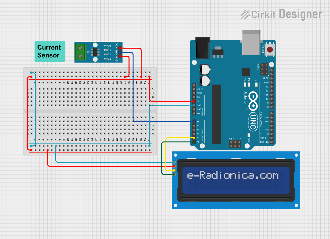
Example: Connecting to an Arduino UNO

Below is an example of how to use a current sensor with an Arduino UNO to measure current and display the value on the Serial Monitor.

// Example code for interfacing a current sensor with Arduino UNO
// Assumes a sensor with 66 mV/A sensitivity and 2.5 V zero-current offset

const int sensorPin = A0;  // Analog pin connected to the sensor's Vout
const float sensitivity = 0.066;  // Sensor sensitivity in V/A (66 mV/A)
const float zeroCurrentOffset = 2.5;  // Zero-current output voltage in volts

void setup() {
  Serial.begin(9600);  // Initialize Serial Monitor at 9600 baud
}

void loop() {
  int sensorValue = analogRead(sensorPin);  // Read the analog value (0-1023)
  float voltage = sensorValue * (5.0 / 1023.0);  // Convert to voltage (0-5 V)
  float current = (voltage - zeroCurrentOffset) / sensitivity;  
  // Calculate current in amps
  
  Serial.print("Current: ");
  Serial.print(current, 2);  // Print current with 2 decimal places
  Serial.println(" A");  // Append unit (Amps)
  
  delay(1000);  // Wait 1 second before next reading
}

Troubleshooting and FAQs

Common Issues Users Might Face

  1. No Output Signal:

    • Ensure the sensor is powered correctly (check Vcc and GND connections).
    • Verify that the current being measured is within the sensor's range.
  2. Inaccurate Readings:

    • Check for noise in the output signal and add a filter capacitor if necessary.
    • Ensure the sensor is properly calibrated for your application.
    • Verify that the wire carrying the current is correctly positioned in the sensing region.
  3. Output Voltage Stuck at Zero:

    • Confirm that the load is drawing current.
    • Inspect the connections for loose or broken wires.

Solutions and Tips for Troubleshooting

  • Use a multimeter to verify the sensor's output voltage and compare it with expected values.
  • If using an Arduino, ensure the analog pin is functioning correctly by testing it with a known voltage source.
  • For Hall-effect sensors, avoid placing them near strong magnetic fields or ferromagnetic materials that could distort the measurement.

By following these guidelines and best practices, you can effectively use a current sensor in your projects and ensure accurate and reliable current measurements.