How to Use LW-K3010D Switching Power Supply: Examples, Pinouts, and Specs
Introduction
The LW-K3010D Switching Power Supply is a compact and efficient device designed to convert AC voltage into a stable DC output. It is widely used in electronics laboratories, repair workshops, and educational environments due to its reliability and precision. This power supply is ideal for powering various electronic devices and circuits, offering adjustable voltage and current settings to meet diverse requirements.
Explore Projects Built with LW-K3010D Switching Power Supply


Explore Projects Built with LW-K3010D Switching Power Supply
Common Applications and Use Cases
- Powering and testing electronic circuits
- Charging batteries with controlled voltage and current
- Educational purposes in electronics labs
- Repair and troubleshooting of electronic devices
- Prototyping and development of electronic projects
Technical Specifications
The LW-K3010D is designed to deliver stable and adjustable DC power with the following key specifications:
| Parameter | Specification |
|---|---|
| Input Voltage | 110V/220V AC ±10%, 50/60Hz |
| Output Voltage Range | 0-30V DC |
| Output Current Range | 0-10A DC |
| Output Power | 300W |
| Voltage Regulation | ≤0.01% + 3mV |
| Current Regulation | ≤0.2% + 3mA |
| Ripple and Noise | ≤1mVrms |
| Display Type | Dual LED display (voltage and current) |
| Cooling Method | Intelligent fan cooling |
| Protection Features | Overload, short circuit, over-temperature |
| Dimensions | 260mm x 155mm x 85mm |
| Weight | Approx. 2.5kg |
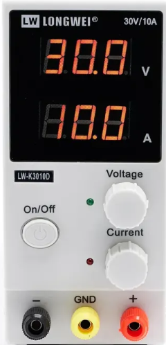
Front Panel Pin Configuration and Descriptions
The LW-K3010D features a user-friendly front panel with the following key components:
| Label | Description |
|---|---|
| V+ (Positive Output) | Positive terminal for DC output voltage |
| V- (Negative Output) | Negative terminal for DC output voltage |
| Voltage Knob | Adjusts the output voltage |
| Current Knob | Adjusts the output current |
| Power Switch | Turns the power supply on or off |
| LED Display | Displays real-time voltage and current readings |
Usage Instructions
How to Use the LW-K3010D in a Circuit
Setup and Safety Check:
- Ensure the power supply is switched off before connecting it to the AC mains.
- Verify that the input voltage matches the power supply's rated input (110V or 220V AC).
- Connect the positive (V+) and negative (V-) terminals to the load or circuit.
Adjusting Voltage and Current:
- Turn on the power supply using the power switch.
- Use the Voltage Knob to set the desired output voltage.
- Use the Current Knob to set the maximum allowable current for the load.
- Monitor the output values on the LED display.
Operating the Load:
- Once the voltage and current are set, power the connected load.
- Observe the LED display to ensure the output remains stable.
Shutdown:
- Turn off the power supply using the power switch.
- Disconnect the load and unplug the power supply from the AC mains.
Important Considerations and Best Practices
- Always set the current limit to protect sensitive components in your circuit.
- Avoid short-circuiting the output terminals to prevent damage to the power supply.
- Ensure proper ventilation around the power supply to prevent overheating.
- Use appropriate cables and connectors rated for the desired current.
Example: Using LW-K3010D with an Arduino UNO
The LW-K3010D can be used to power an Arduino UNO by providing a stable 5V DC output. Below is an example of how to connect and use it:
- Set the output voltage to 5V using the Voltage Knob.
- Set the current limit to 1A using the Current Knob.
- Connect the V+ terminal to the Arduino's VIN pin and the V- terminal to the GND pin.
- Power on the Arduino and verify its operation.
// Example Arduino code to blink an LED
// Connect an LED to pin 13 with a 220-ohm resistor

void setup() {
  pinMode(13, OUTPUT); // Set pin 13 as an output
}

void loop() {
  digitalWrite(13, HIGH); // Turn the LED on
  delay(1000);            // Wait for 1 second
  digitalWrite(13, LOW);  // Turn the LED off
  delay(1000);            // Wait for 1 second
}
Troubleshooting and FAQs
Common Issues and Solutions
| Issue | Possible Cause | Solution |
|---|---|---|
| No output voltage | Power supply not turned on | Ensure the power switch is in the ON position. |
| Output voltage fluctuates | Load exceeds current limit | Increase the current limit or reduce the load. |
| Overheating | Insufficient ventilation | Ensure proper airflow and avoid blocking vents. |
| Short circuit protection triggered | Output terminals shorted | Check and correct the wiring connections. |
FAQs
Can I use the LW-K3010D to charge batteries?
- Yes, but ensure the voltage and current settings match the battery's specifications.
What happens if the load exceeds the current limit?
- The power supply will enter constant current mode, limiting the output current to the set value.
Is the LW-K3010D suitable for sensitive electronics?
- Yes, its low ripple and noise make it ideal for powering sensitive devices.
By following this documentation, users can safely and effectively operate the LW-K3010D Switching Power Supply for a variety of applications.