How to Use 5x7 pin board: Examples, Pinouts, and Specs
Introduction
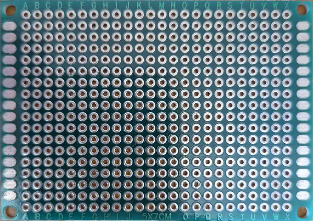
The 5x7 pin board is a compact, perforated prototyping board designed for building and testing electronic circuits. It features a grid of 5 rows and 7 columns of holes, enabling users to insert electronic components and jumper wires to create temporary or semi-permanent circuit connections. This board is ideal for quick prototyping, educational purposes, and small-scale circuit designs.
Explore Projects Built with 5x7 pin board


Explore Projects Built with 5x7 pin board
Common Applications and Use Cases
- Rapid prototyping of electronic circuits
- Educational projects for learning circuit design
- Testing and debugging small-scale circuits
- Temporary setups for proof-of-concept designs
- DIY electronics and hobbyist projects
Technical Specifications
The 5x7 pin board is a simple yet versatile tool. Below are its key technical details:
| Specification | Details |
|---|---|
| Material | FR4 (fiberglass) or phenolic resin |
| Dimensions | Approximately 5 cm x 7 cm |
| Hole Grid | 5 rows x 7 columns |
| Hole Diameter | ~1 mm (suitable for standard pins) |
| Hole Spacing | 2.54 mm (0.1 inch) |
| Compatibility | Standard through-hole components |
| Surface Finish | Copper pads (optional, depending on model) |
Pin Configuration and Descriptions
The 5x7 pin board does not have predefined pin configurations, as it is a general-purpose prototyping tool. However, the grid layout allows for flexible placement of components and connections. Below is a representation of the grid:
| Row | Column 1 | Column 2 | Column 3 | Column 4 | Column 5 | Column 6 | Column 7 |
|---|---|---|---|---|---|---|---|
| 1 | Hole | Hole | Hole | Hole | Hole | Hole | Hole |
| 2 | Hole | Hole | Hole | Hole | Hole | Hole | Hole |
| 3 | Hole | Hole | Hole | Hole | Hole | Hole | Hole |
| 4 | Hole | Hole | Hole | Hole | Hole | Hole | Hole |
| 5 | Hole | Hole | Hole | Hole | Hole | Hole | Hole |
Each hole in the grid is plated or unplated (depending on the model) and can accommodate standard through-hole components or jumper wires.
Usage Instructions
How to Use the 5x7 Pin Board in a Circuit
- Plan Your Circuit: Sketch the circuit diagram and decide the placement of components on the board.
- Insert Components: Place through-hole components (e.g., resistors, capacitors, ICs) into the holes of the board.
- Connect Components: Use jumper wires or solder to connect the components as per your circuit design.
- Test the Circuit: Power the circuit and test its functionality. Make adjustments as needed.
Important Considerations and Best Practices
- Component Placement: Ensure components are placed in a way that minimizes wire crossings and clutter.
- Jumper Wires: Use color-coded jumper wires to make connections easier to trace.
- Soldering (Optional): For semi-permanent setups, solder the components and wires to the board.
- Power Supply: Verify that the power supply voltage and current are within the limits of your components.
- Avoid Overcrowding: Leave enough space between components to prevent accidental short circuits.
Example: Connecting an LED to an Arduino UNO
The 5x7 pin board can be used to prototype simple circuits, such as connecting an LED to an Arduino UNO. Below is an example:
Circuit Description
- Connect an LED to pin 13 of the Arduino UNO through a 220-ohm resistor.
- Use the 5x7 pin board to organize the components.
Code Example
// Arduino code to blink an LED connected to pin 13
// Ensure the LED's longer leg (anode) is connected to pin 13
// and the shorter leg (cathode) is connected to GND via a resistor.

void setup() {
  pinMode(13, OUTPUT); // Set pin 13 as an output pin
}

void loop() {
  digitalWrite(13, HIGH); // Turn the LED on
  delay(1000);            // Wait for 1 second
  digitalWrite(13, LOW);  // Turn the LED off
  delay(1000);            // Wait for 1 second
}
Troubleshooting and FAQs
Common Issues and Solutions
Loose Connections:
- Issue: Components or wires are not making proper contact with the board.
- Solution: Ensure components are firmly inserted into the holes. Use jumper wires with proper pin thickness.
Short Circuits:
- Issue: Adjacent wires or components are accidentally touching.
- Solution: Check for overlapping wires and ensure proper spacing between components.
Component Overheating:
- Issue: Components heat up during operation.
- Solution: Verify that the power supply voltage and current are within the component's specifications.
Unstable Circuit Behavior:
- Issue: The circuit does not function as expected.
- Solution: Double-check the circuit connections against the schematic. Ensure all components are functional.
FAQs
Q: Can I solder components to the 5x7 pin board?
A: Yes, you can solder components for a more permanent setup. However, ensure the board is designed for soldering (e.g., with copper pads).
Q: What types of components can I use with this board?
A: The 5x7 pin board is compatible with standard through-hole components, such as resistors, capacitors, LEDs, transistors, and ICs.
Q: Is the board reusable?
A: Yes, the board is reusable if components are not soldered. Simply remove the components and wires to use it for another project.
Q: Can I use this board for high-power circuits?
A: The 5x7 pin board is best suited for low-power circuits. For high-power applications, ensure proper insulation and spacing to prevent overheating or damage.
This documentation provides a comprehensive guide to using the 5x7 pin board effectively for your prototyping needs. Happy building!