Cirkit Designer
Your all-in-one circuit design IDE
Home /
Component Documentation
How to Use TCS230: Examples, Pinouts, and Specs
Introduction
The TCS230 is a programmable color light-to-frequency converter, which combines configurable silicon photodiodes and a current-to-frequency converter on a single monolithic CMOS integrated circuit. This sensor is widely used in various applications such as color sorting, ambient light sensing, and color matching in consumer electronics.
Explore Projects Built with TCS230
ESP8266 NodeMCU Controlled TCS3200 Color Sensor Interface
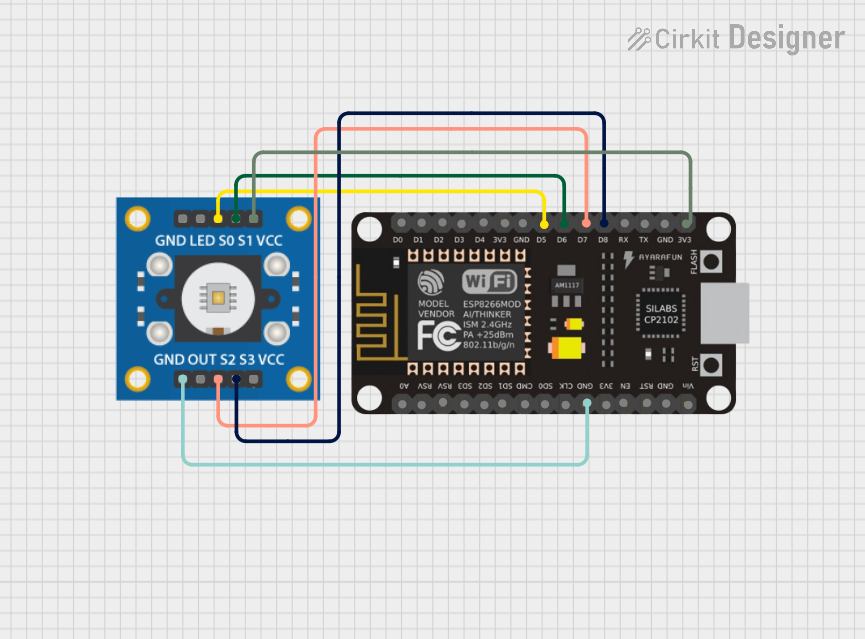
This circuit connects an ESP8266 NodeMCU microcontroller to a TCS3200 color sensor. The NodeMCU's digital pins D5, D6, D7, and D8 are interfaced with the TCS3200's S0, S1, S2, and S3 pins respectively, allowing the microcontroller to control the color sensor's filtering and frequency scaling. Power is supplied to the TCS3200 from the NodeMCU's 3.3V pin, and both devices share a common ground.
ESP32-Based Color and Weight Sensing System with IR Detection
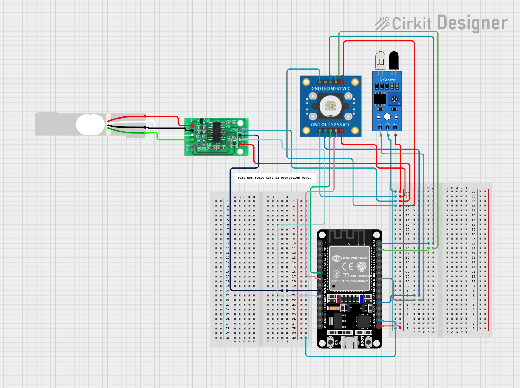
This circuit is designed to interface an ESP32 microcontroller with a TCS3200 color sensor, an IR sensor for proximity detection, and an HX711 load cell amplifier connected to a load cell for weight measurement. It is capable of performing color recognition, object detection, and weight measurement, making it suitable for sorting systems or interactive projects.
Arduino Nano-Based Smart Weighing System with Color Sensor and Servo Control
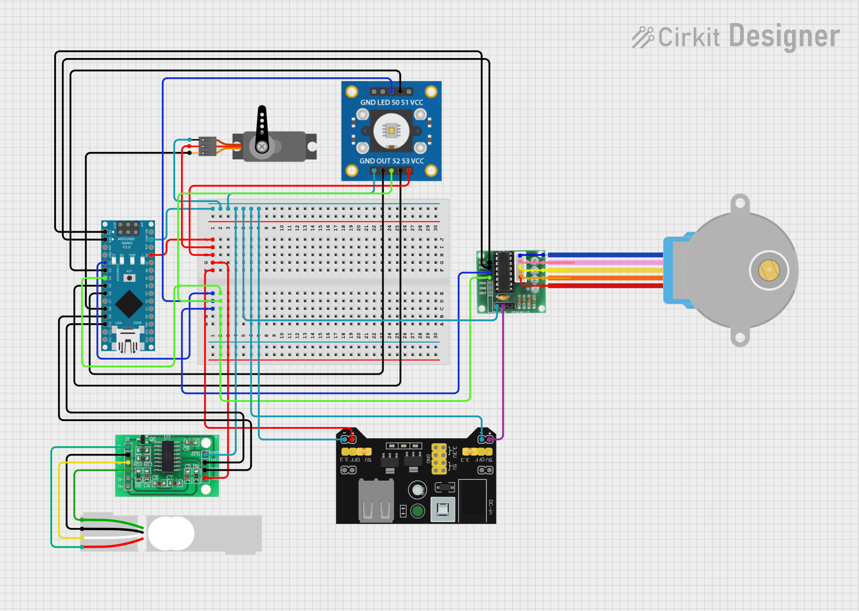
This circuit is a multi-functional system that includes an Arduino Nano to control a TCS3200 color sensor, a servo motor, a load cell with an HX711 interface, and a 28BYJ-48 stepper motor driven by a ULN2003 driver. The system is powered by an MB102 breadboard power supply module and is designed for applications requiring color detection, precise motor control, and weight measurement.
ESP8266 NodeMCU Controlled Multi-Channel Thermocouple Interface

This circuit is designed to interface multiple MAX6675 thermocouple-to-digital converter modules with an ESP8266 NodeMCU microcontroller. Each MAX6675 module is connected to a temperature sensor and the ESP8266 is configured to communicate with the modules via SPI to read temperature data. The ESP8266 NodeMCU manages the chip select (CS) lines individually for each MAX6675 module, allowing for multiple temperature readings from different sensors.
Explore Projects Built with TCS230
ESP8266 NodeMCU Controlled TCS3200 Color Sensor Interface
This circuit connects an ESP8266 NodeMCU microcontroller to a TCS3200 color sensor. The NodeMCU's digital pins D5, D6, D7, and D8 are interfaced with the TCS3200's S0, S1, S2, and S3 pins respectively, allowing the microcontroller to control the color sensor's filtering and frequency scaling. Power is supplied to the TCS3200 from the NodeMCU's 3.3V pin, and both devices share a common ground.
ESP32-Based Color and Weight Sensing System with IR Detection
This circuit is designed to interface an ESP32 microcontroller with a TCS3200 color sensor, an IR sensor for proximity detection, and an HX711 load cell amplifier connected to a load cell for weight measurement. It is capable of performing color recognition, object detection, and weight measurement, making it suitable for sorting systems or interactive projects.
Arduino Nano-Based Smart Weighing System with Color Sensor and Servo Control
This circuit is a multi-functional system that includes an Arduino Nano to control a TCS3200 color sensor, a servo motor, a load cell with an HX711 interface, and a 28BYJ-48 stepper motor driven by a ULN2003 driver. The system is powered by an MB102 breadboard power supply module and is designed for applications requiring color detection, precise motor control, and weight measurement.
ESP8266 NodeMCU Controlled Multi-Channel Thermocouple Interface
This circuit is designed to interface multiple MAX6675 thermocouple-to-digital converter modules with an ESP8266 NodeMCU microcontroller. Each MAX6675 module is connected to a temperature sensor and the ESP8266 is configured to communicate with the modules via SPI to read temperature data. The ESP8266 NodeMCU manages the chip select (CS) lines individually for each MAX6675 module, allowing for multiple temperature readings from different sensors.
Common Applications and Use Cases
- Color sorting machines
- Ambient light sensing for display backlight control
- Color matching in printing industry
- DIY projects involving color detection, such as robotics and art installations
Technical Specifications
Key Technical Details
- Supply Voltage (Vdd): 2.7V to 5.5V
- Output Frequency: Programmable from typically 2Hz to 500kHz
- Photodiode Array: 8x8 (64 diodes total)
- 16 photodiodes with red filters
- 16 photodiodes with green filters
- 16 photodiodes with blue filters
- 16 photodiodes without filter (clear)
- On-chip Photodiode Types: Red, Green, Blue (RGB), and Clear light sensing
- Output Type: Square wave (50% duty cycle) with frequency directly proportional to light intensity (irradiance)
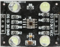
Pin Configuration and Descriptions
| Pin Number | Name | Description |
|---|---|---|
| 1 | Vdd | Power supply (2.7V to 5.5V) |
| 2 | S0 | Output frequency scaling selection inputs |
| 3 | S1 | Output frequency scaling selection inputs |
| 4 | S2 | Photodiode type selection input |
| 5 | S3 | Photodiode type selection input |
| 6 | OUT | Output frequency (square wave) |
| 7 | OE | Output enable (active low) |
| 8 | GND | Ground |
Usage Instructions
How to Use the TCS230 in a Circuit
- Power Supply: Connect the Vdd pin to a 2.7V to 5.5V power supply and the GND pin to the ground.
- Frequency Scaling: Set the S0 and S1 pins to configure the output frequency scaling (power-down, 2%, 20%, or 100% of the original scaling).
- Photodiode Selection: Use the S2 and S3 pins to select which type of photodiodes (red, green, blue, or clear) are active.
- Output Enable: Connect the OE pin to ground to enable the output frequency, or to a logic high level to disable it.
- Reading the Output: Connect the OUT pin to a frequency counter or a microcontroller to read the output frequency.
Important Considerations and Best Practices
- Ensure that the power supply voltage is within the specified range to prevent damage.
- Use a bypass capacitor (typically 0.1 µF) between Vdd and GND near the sensor to filter out noise.
- Avoid exposing the sensor to direct sunlight or strong artificial light sources that may saturate the photodiodes.
- Calibrate the sensor for the specific application environment to achieve accurate color detection.
Troubleshooting and FAQs
Common Issues Users Might Face
- Inaccurate Color Detection: Ensure that the sensor is properly calibrated for the ambient light conditions.
- No Output Signal: Check the power supply and connections. Ensure that the OE pin is not floating and is properly set to enable the output.
- Erratic Readings: Ensure that there is no electrical noise affecting the sensor. Use a bypass capacitor and keep the power supply stable.
Solutions and Tips for Troubleshooting
- Calibration: Perform a white and black calibration procedure to set the maximum and minimum frequency values corresponding to the colors.
- Light Conditions: Operate the sensor in consistent lighting conditions or implement an algorithm to compensate for changes in ambient light.
- Connection Issues: Verify all connections, especially the OE pin, and ensure that the pins are not shorted.
Example Arduino Code
// Example code for interfacing TCS230 color sensor with Arduino UNO

#include <Wire.h>

// Define the TCS230 sensor pins
#define S0 4
#define S1 5
#define S2 6
#define S3 7
#define OUT 8

void setup() {
  pinMode(S0, OUTPUT);
  pinMode(S1, OUTPUT);
  pinMode(S2, OUTPUT);
  pinMode(S3, OUTPUT);
  pinMode(OUT, INPUT);

  // Set frequency scaling to 20%
  digitalWrite(S0, HIGH);
  digitalWrite(S1, LOW);

  Serial.begin(9600);
}

void loop() {
  // Read the frequency of the red, green, and blue photodiodes
  int redFrequency = readColorFrequency(LOW, LOW);
  int greenFrequency = readColorFrequency(HIGH, HIGH);
  int blueFrequency = readColorFrequency(LOW, HIGH);

  // Print the results
  Serial.print("R: ");
  Serial.print(redFrequency);
  Serial.print(" G: ");
  Serial.print(greenFrequency);
  Serial.print(" B: ");
  Serial.println(blueFrequency);

  delay(1000);
}

int readColorFrequency(boolean s2, boolean s3) {
  digitalWrite(S2, s2);
  digitalWrite(S3, s3);
  // Wait for the sensor to stabilize
  delay(100);
  // Read the pulse frequency from the TCS230 sensor
  int count = pulseIn(OUT, LOW);
  return count;
}
Note: The above code is a simple example to get started with the TCS230 sensor. For accurate color detection, you will need to implement calibration and possibly more sophisticated algorithms to interpret the sensor readings based on your specific application needs.