
How to Use disjoncteur 2P 63A: Examples, Pinouts, and Specs
 Design with disjoncteur 2P 63A in Cirkit Designer
Introduction
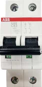
The Disjoncteur 2P 63A is a 2-pole circuit breaker rated for a maximum current of 63 amps. It is designed to protect electrical circuits from overloads and short circuits by automatically disconnecting the power supply when unsafe conditions are detected. This component is widely used in residential, commercial, and industrial electrical systems to ensure safety and prevent damage to equipment.
Explore Projects Built with disjoncteur 2P 63A
 Open Project in Cirkit Designer
 Open Project in Cirkit Designer
 Open Project in Cirkit Designer
 Open Project in Cirkit Designer
Explore Projects Built with disjoncteur 2P 63A
Open Project in Cirkit DesignerOpen Project in Cirkit DesignerOpen Project in Cirkit DesignerOpen Project in Cirkit DesignerCommon Applications and Use Cases
- Protection of electrical circuits in homes, offices, and industrial facilities.
- Safeguarding appliances and equipment from overcurrent and short circuits.
- Use in distribution boards for isolating and protecting specific circuits.
- Ensuring compliance with electrical safety standards.
Technical Specifications
The following table outlines the key technical details of the Disjoncteur 2P 63A:
| Parameter | Value |
|---|---|
| Rated Current (In) | 63 A |
| Number of Poles | 2 |
| Rated Voltage (Un) | 230/400 V AC |
| Breaking Capacity (Icu) | 6 kA |
| Frequency | 50/60 Hz |
| Trip Curve | Type C (standard) |
| Mounting Type | DIN rail |
| Operating Temperature | -5°C to +40°C |
| Standards Compliance | IEC 60898-1 |
Pin Configuration and Descriptions
The Disjoncteur 2P 63A has two input terminals and two output terminals. The table below describes the terminal connections:
| Terminal | Description |
|---|---|
| L1 (Input) | Live input for the first pole |
| L2 (Input) | Live input for the second pole |
| L1 (Output) | Live output for the first pole |
| L2 (Output) | Live output for the second pole |
Usage Instructions
How to Use the Component in a Circuit
Mounting the Circuit Breaker:
- Install the Disjoncteur 2P 63A on a standard DIN rail in the distribution board.
- Ensure the breaker is securely locked into place.
Wiring the Circuit Breaker:
- Connect the live wires from the power source to the input terminals (L1 and L2).
- Connect the output terminals (L1 and L2) to the load or downstream circuit.
- Tighten all terminal screws to ensure a secure connection.
Testing the Circuit Breaker:
- After installation, switch the breaker to the "ON" position.
- Test the breaker by simulating an overload or short circuit (if safe to do so) to ensure it trips correctly.
Important Considerations and Best Practices
- Current Rating: Ensure the connected load does not exceed the rated current of 63 A.
- Trip Curve: The Type C trip curve is suitable for general-purpose applications. For specialized loads, consult the manufacturer.
- Environmental Conditions: Avoid installing the breaker in environments with extreme temperatures or high humidity.
- Regular Maintenance: Periodically inspect the breaker for signs of wear, loose connections, or damage.
Example: Connecting to an Arduino-Controlled Relay
While the Disjoncteur 2P 63A is not directly controlled by microcontrollers like Arduino, it can be used in conjunction with an Arduino-controlled relay to automate circuit control. Below is an example of Arduino code to control a relay that switches the circuit breaker:
// Arduino code to control a relay for automating circuit breaker operation
const int relayPin = 7; // Pin connected to the relay module

void setup() {
  pinMode(relayPin, OUTPUT); // Set relay pin as output
  digitalWrite(relayPin, LOW); // Ensure relay is off at startup
}

void loop() {
  // Example: Turn the relay on for 5 seconds, then off
  digitalWrite(relayPin, HIGH); // Activate relay (close circuit)
  delay(5000); // Wait for 5 seconds
  digitalWrite(relayPin, LOW); // Deactivate relay (open circuit)
  delay(5000); // Wait for 5 seconds
}
Note: Ensure the relay module is rated for the voltage and current of the circuit being controlled. The relay should only control the circuit breaker indirectly (e.g., by switching power to the load).
Troubleshooting and FAQs
Common Issues Users Might Face
Circuit Breaker Does Not Trip:
- Cause: The load current is below the trip threshold.
- Solution: Verify the load current and ensure it exceeds the trip threshold during testing.
Frequent Tripping:
- Cause: Overloaded circuit or short circuit in the wiring.
- Solution: Reduce the load or inspect the wiring for faults.
Loose Connections:
- Cause: Terminal screws are not tightened properly.
- Solution: Recheck and tighten all terminal screws.
Breaker Does Not Reset:
- Cause: Persistent fault in the circuit or damaged breaker.
- Solution: Inspect the circuit for faults and replace the breaker if necessary.
Solutions and Tips for Troubleshooting
- Always turn off the main power supply before inspecting or troubleshooting the circuit breaker.
- Use a multimeter to check for continuity and measure current or voltage in the circuit.
- If the breaker trips repeatedly, consult a licensed electrician to identify and resolve the issue.
By following this documentation, users can safely and effectively install, use, and maintain the Disjoncteur 2P 63A in their electrical systems.