How to Use CCMHC 10A DC Motor Speed Controller (PWM): Examples, Pinouts, and Specs
Introduction
The CCMHC 10A DC Motor Speed Controller is an electronic device designed to control the speed of a DC motor using Pulse Width Modulation (PWM) technique. It is capable of handling currents up to 10A, making it suitable for a wide range of applications including robotics, DIY projects, and industrial automation systems.
Explore Projects Built with CCMHC 10A DC Motor Speed Controller (PWM)


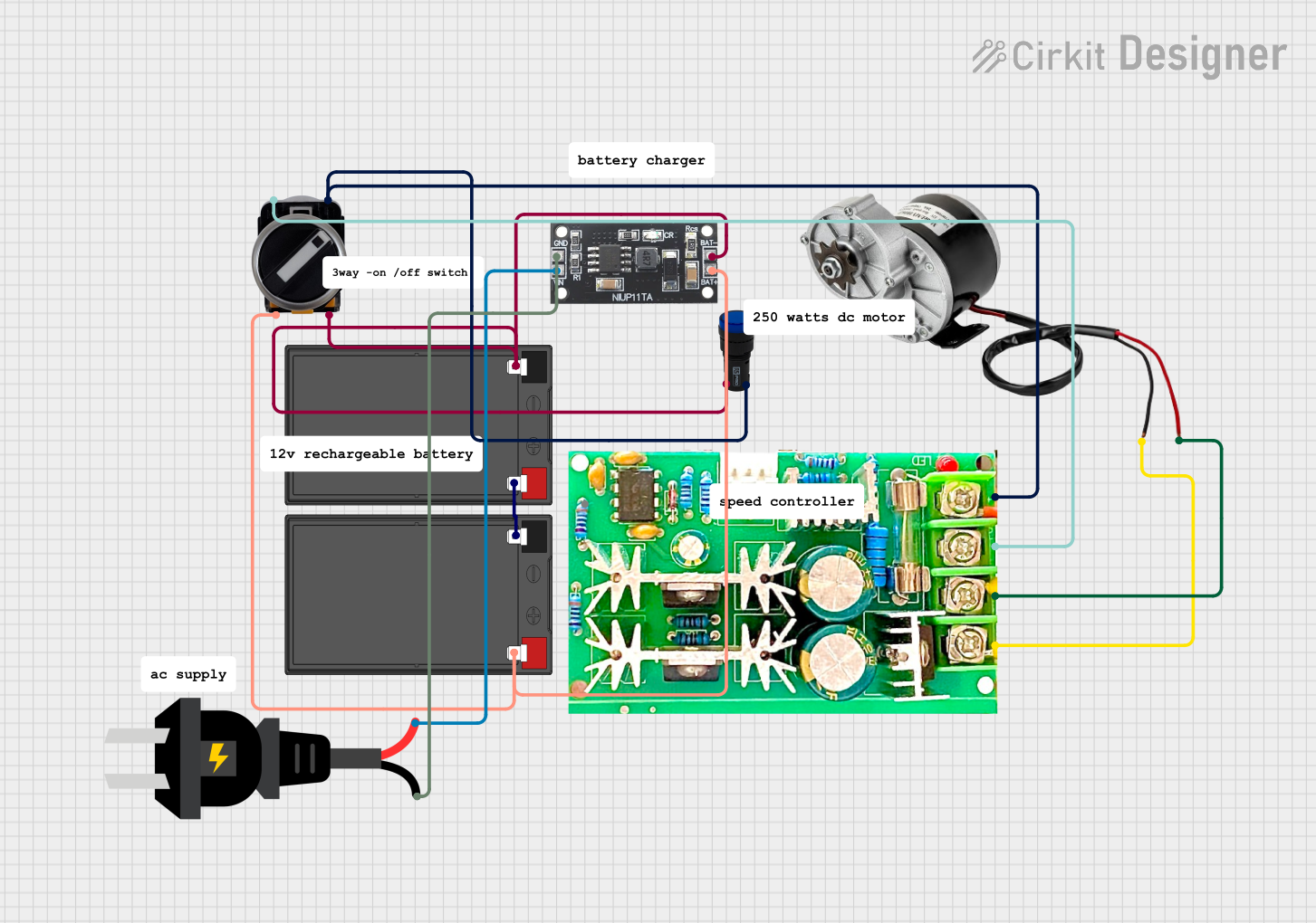
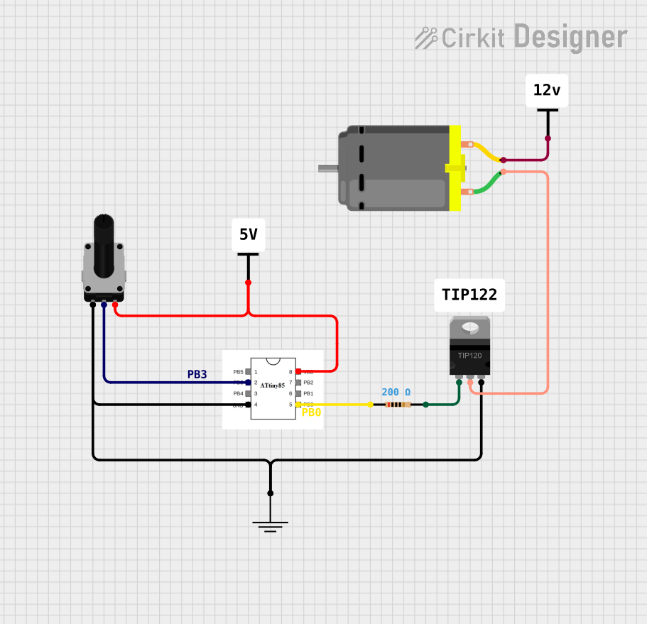
Explore Projects Built with CCMHC 10A DC Motor Speed Controller (PWM)
Common Applications and Use Cases
- Speed control for DC motors in toys and models
- Fan speed regulation
- Conveyor belt speed control
- Automotive applications for controlling pumps or blowers
Technical Specifications
Key Technical Details
- Input Voltage: 6V to 28V DC
- Output Current: 0 to 10A (max)
- PWM Frequency: 21kHz
- Duty Cycle: 0% to 100%
- Control Method: Potentiometer (10k ohm)
- Efficiency: >95%
- Operating Temperature: -20°C to 40°C
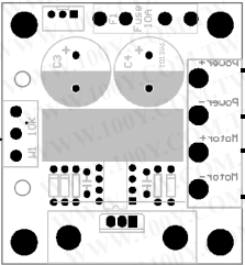
Pin Configuration and Descriptions
| Pin Number | Description | Notes |
|---|---|---|
| 1 | V+ (Power Supply) | Connect to positive of battery |
| 2 | Motor Output (+) | Connect to positive of motor |
| 3 | Motor Output (-) | Connect to negative of motor |
| 4 | GND (Ground) | Connect to negative of battery |
Usage Instructions
How to Use the Component in a Circuit
- Connect the power supply to the V+ and GND pins, ensuring that the voltage is within the specified range.
- Connect the DC motor to the Motor Output pins (+ and -).
- Adjust the potentiometer to vary the motor speed.
Important Considerations and Best Practices
- Ensure that the current does not exceed the 10A maximum rating to prevent damage.
- Use a heat sink if operating near the maximum current rating for extended periods.
- Avoid rapid changes in motor direction to prevent mechanical stress and potential damage to the motor.
Troubleshooting and FAQs
Common Issues Users Might Face
- Motor not spinning: Check connections and power supply voltage.
- Motor speed not adjusting: Verify that the potentiometer is functioning and properly connected.
- Controller overheating: Reduce the load or improve cooling.
Solutions and Tips for Troubleshooting
- Double-check wiring and solder joints for any loose connections or shorts.
- Measure the input voltage with a multimeter to ensure it falls within the specified range.
- If the motor speed does not change, replace the potentiometer.
Arduino UNO Connection Example
To control the CCMHC 10A DC Motor Speed Controller with an Arduino UNO, you can use the following code snippet. This example assumes you are using a digital pin with PWM capability to control the speed of the motor.
// Define the PWM pin connected to the speed controller
const int pwmPin = 3; // Use a PWM pin

void setup() {
  // Set the PWM pin as an output
  pinMode(pwmPin, OUTPUT);
}

void loop() {
  // Set the motor speed to half of its maximum speed
  analogWrite(pwmPin, 128); // 128 out of 255 is approximately 50%

  delay(2000); // Run at this speed for 2 seconds

  // Stop the motor
  analogWrite(pwmPin, 0); // 0 stops the motor

  delay(1000); // Stop for 1 second

  // Set the motor speed to full speed
  analogWrite(pwmPin, 255); // 255 sets the motor to its maximum speed

  delay(2000); // Run at this speed for 2 seconds

  // Repeat the cycle
}
Note: The PWM frequency of the Arduino UNO is different from the PWM frequency of the CCMHC controller. This may result in a different motor behavior than when using the potentiometer directly on the controller.
Remember to adjust the pwmPin variable to match the pin you are using on your Arduino UNO. The analogWrite function is used to send a PWM signal to the motor controller, which in turn controls the speed of the motor.