
How to Use ZMPT101B: Examples, Pinouts, and Specs
 Design with ZMPT101B in Cirkit Designer
Introduction
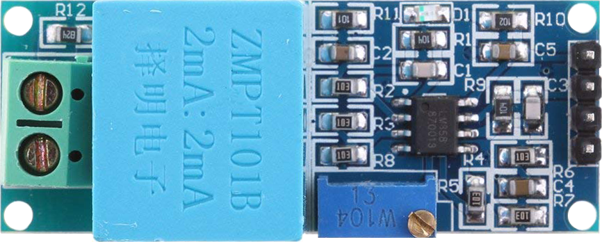
The ZMPT101B is a precision voltage transformer module designed for measuring AC voltage. It provides an isolated output proportional to the input voltage, ensuring safety and accuracy in voltage measurement applications. This module is widely used in power monitoring, energy metering, and other applications requiring precise AC voltage measurement.
Explore Projects Built with ZMPT101B
 Open Project in Cirkit Designer
 Open Project in Cirkit Designer
 Open Project in Cirkit Designer
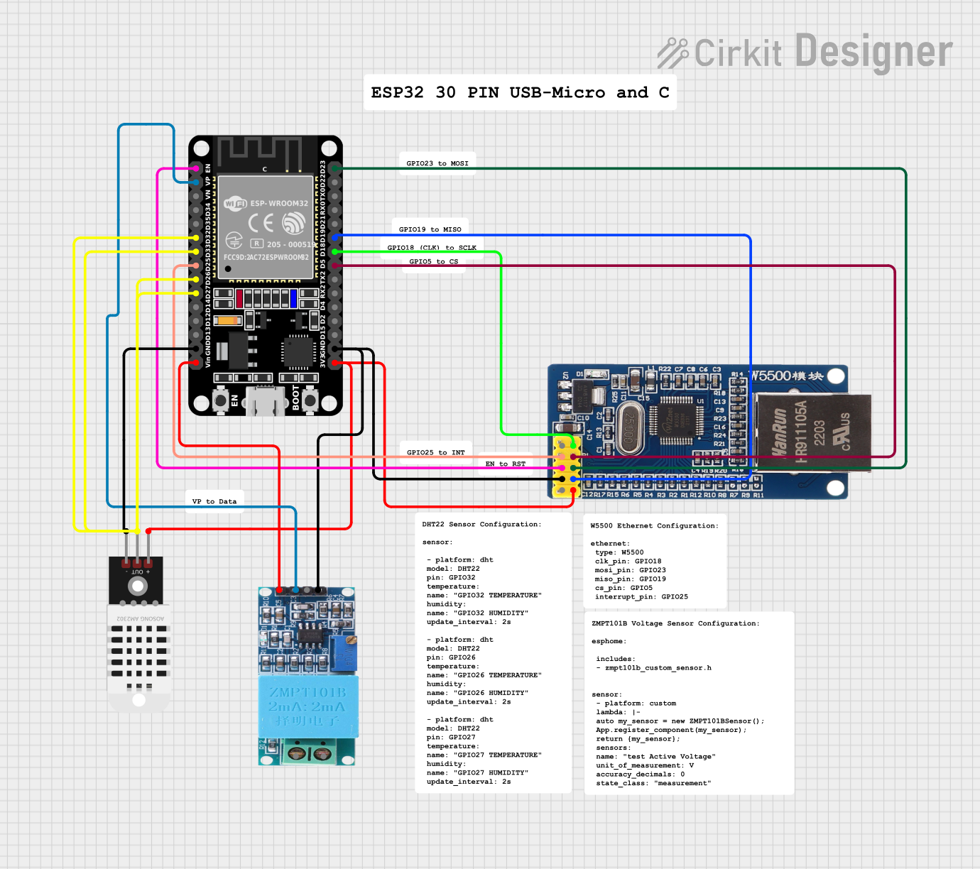 Open Project in Cirkit Designer
Explore Projects Built with ZMPT101B
Open Project in Cirkit DesignerOpen Project in Cirkit DesignerOpen Project in Cirkit DesignerOpen Project in Cirkit DesignerCommon Applications
- Power monitoring systems
- Energy metering devices
- Home automation systems
- Industrial equipment monitoring
- Educational projects involving AC voltage measurement
Technical Specifications
The ZMPT101B module is designed to provide accurate and isolated AC voltage measurements. Below are its key technical details:
Key Specifications
| Parameter | Value |
|---|---|
| Input Voltage Range | 0–250V AC (adjustable) |
| Output Voltage Range | 0–5V DC (proportional output) |
| Operating Voltage | 5V DC |
| Accuracy | High precision |
| Isolation | Galvanic isolation |
| Dimensions | 38mm x 28mm x 19mm |
Pin Configuration
The ZMPT101B module has a simple pinout for easy integration into circuits. Below is the pin configuration:
| Pin Name | Description |
|---|---|
| VCC | Power supply input (5V DC) |
| GND | Ground |
| OUT | Analog output voltage (proportional to AC input) |
Usage Instructions
The ZMPT101B module is straightforward to use in circuits. Follow the steps below to integrate it into your project:
Connecting the ZMPT101B
- Power Supply: Connect the
VCCpin to a 5V DC power source and theGNDpin to ground. - AC Voltage Input: Connect the AC voltage source to the input terminals of the ZMPT101B module.
- Output Signal: Connect the
OUTpin to an analog input pin of a microcontroller (e.g., Arduino) to read the proportional voltage.
Important Considerations
- Calibration: The module includes a potentiometer for calibration. Adjust it to ensure accurate voltage readings.
- Isolation: The ZMPT101B provides galvanic isolation, but ensure proper insulation and safety precautions when working with high-voltage AC inputs.
- Filtering: Use additional filtering (e.g., capacitors) if the output signal is noisy.
- Voltage Range: Ensure the input AC voltage does not exceed the module's rated range.
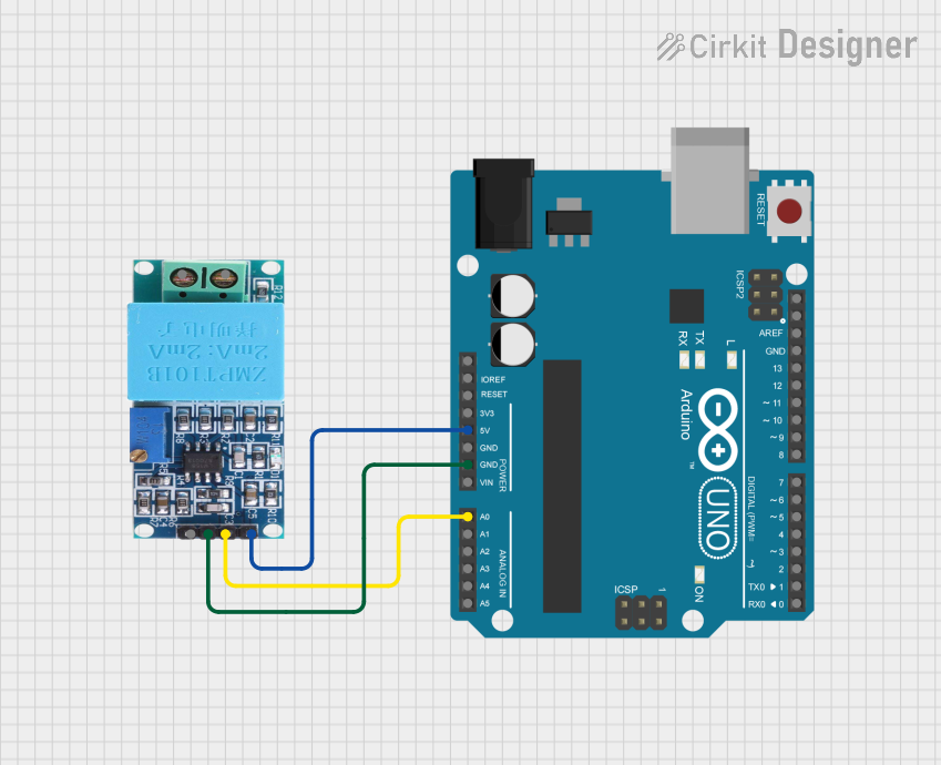
Example: Using ZMPT101B with Arduino UNO
Below is an example of how to use the ZMPT101B module with an Arduino UNO to measure AC voltage:
// Include necessary libraries
const int analogPin = A0; // Connect ZMPT101B OUT pin to Arduino A0
float calibrationFactor = 100.0; // Adjust based on calibration

void setup() {
  Serial.begin(9600); // Initialize serial communication
}

void loop() {
  int sensorValue = analogRead(analogPin); // Read analog value from ZMPT101B
  float voltage = (sensorValue / 1023.0) * 5.0; // Convert to voltage (0-5V range)

  // Calculate AC voltage using calibration factor
  float acVoltage = voltage * calibrationFactor;

  // Print the measured AC voltage
  Serial.print("AC Voltage: ");
  Serial.print(acVoltage);
  Serial.println(" V");

  delay(1000); // Wait for 1 second before next reading
}
Best Practices
- Always calibrate the module before use to ensure accurate readings.
- Avoid exposing the module to moisture or extreme temperatures.
- Use proper insulation and safety measures when working with high-voltage AC inputs.
Troubleshooting and FAQs
Common Issues and Solutions
| Issue | Possible Cause | Solution |
|---|---|---|
| No output signal | Incorrect wiring | Verify connections to VCC, GND, and OUT. |
| Inaccurate voltage readings | Calibration not performed | Adjust the potentiometer for calibration. |
| Noisy output signal | Electrical interference or noise | Add filtering capacitors to the circuit. |
| Module overheating | Input voltage exceeds rated range | Ensure input voltage is within limits. |
FAQs
Q1: Can the ZMPT101B measure DC voltage?
A1: No, the ZMPT101B is designed specifically for AC voltage measurement.
Q2: How do I calibrate the ZMPT101B module?
A2: Use the onboard potentiometer to adjust the output voltage until it matches the expected value for a known AC input.
Q3: What is the maximum AC voltage the ZMPT101B can measure?
A3: The module can measure up to 250V AC, but ensure proper calibration and safety precautions.
Q4: Can I use the ZMPT101B with a 3.3V microcontroller?
A4: Yes, but you may need to adjust the output scaling or use a level shifter to ensure compatibility.
By following this documentation, you can effectively integrate the ZMPT101B module into your projects for accurate AC voltage measurement.