How to Use 2 BMS: Examples, Pinouts, and Specs
Introduction
A 2S Battery Management System (BMS) is an electronic module designed to manage and protect a 2-cell lithium-ion or lithium-polymer battery pack connected in series. It monitors the battery's state, balances the cells, and ensures safe operation by preventing overcharging, over-discharging, and overcurrent conditions. The 2S BMS is essential for maintaining battery health, optimizing performance, and extending the lifespan of the battery pack.
Explore Projects Built with 2 BMS


Explore Projects Built with 2 BMS
Common Applications and Use Cases
- Power banks and portable chargers
- Electric bicycles and scooters
- Solar energy storage systems
- Robotics and IoT devices
- Uninterruptible Power Supplies (UPS)
Technical Specifications
Below are the key technical details for a typical 2S BMS:
| Parameter | Value |
|---|---|
| Battery Configuration | 2 cells in series (2S) |
| Input Voltage Range | 6.0V to 8.4V |
| Overcharge Protection | 4.25V ± 0.05V per cell |
| Over-discharge Protection | 2.5V ± 0.05V per cell |
| Overcurrent Protection | 3A to 20A (varies by model) |
| Balancing Current | 30mA to 60mA |
| Operating Temperature | -20°C to 60°C |
| Dimensions | Typically 20mm x 40mm x 3mm |
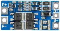
Pin Configuration and Descriptions
The 2S BMS typically has the following pin configuration:
| Pin Name | Description |
|---|---|
| B+ | Positive terminal of the battery pack |
| B- | Negative terminal of the battery pack |
| P+ | Positive terminal of the load or charger |
| P- | Negative terminal of the load or charger |
| BM | Connection point between the two cells in the series (middle connection point) |
Usage Instructions
How to Use the 2S BMS in a Circuit
Connect the Battery Pack:
- Connect the positive terminal of the battery pack to the
B+pin. - Connect the negative terminal of the battery pack to the
B-pin. - Connect the middle point between the two cells to the
BMpin.
- Connect the positive terminal of the battery pack to the
Connect the Load and Charger:
- Connect the positive terminal of the load or charger to the
P+pin. - Connect the negative terminal of the load or charger to the
P-pin.
- Connect the positive terminal of the load or charger to the
Verify Connections:
- Double-check all connections to ensure they are secure and correct.
- Ensure the battery pack voltage is within the supported range of the BMS.
Power On:
- Once all connections are verified, the BMS will automatically start monitoring and protecting the battery pack.
Important Considerations and Best Practices
- Cell Matching: Ensure the cells in the battery pack are of the same type, capacity, and charge level before connecting to the BMS.
- Heat Dissipation: Avoid placing the BMS in an enclosed space without proper ventilation, as it may generate heat during operation.
- Current Rating: Ensure the BMS's current rating matches the load requirements to prevent overcurrent issues.
- Balancing: Allow the BMS to balance the cells periodically to maintain equal voltage levels across the cells.
Example: Using a 2S BMS with an Arduino UNO
To monitor the battery voltage using an Arduino UNO, you can connect the battery pack's positive terminal to an analog input pin through a voltage divider circuit. Below is an example code snippet:
// Arduino code to monitor a 2S battery pack voltage using a voltage divider
const int voltagePin = A0; // Analog pin connected to the voltage divider
const float resistor1 = 10000.0; // Resistor value in ohms (R1)
const float resistor2 = 10000.0; // Resistor value in ohms (R2)
const float referenceVoltage = 5.0; // Arduino reference voltage (5V for UNO)

void setup() {
  Serial.begin(9600); // Initialize serial communication
}

void loop() {
  int analogValue = analogRead(voltagePin); // Read analog value
  float voltage = (analogValue / 1023.0) * referenceVoltage; // Convert to voltage
  float batteryVoltage = voltage * ((resistor1 + resistor2) / resistor2);
  // Calculate battery voltage using voltage divider formula

  Serial.print("Battery Voltage: ");
  Serial.print(batteryVoltage);
  Serial.println(" V");

  delay(1000); // Wait for 1 second before the next reading
}
Note: Use appropriate resistor values in the voltage divider to ensure the input voltage to the Arduino does not exceed 5V.
Troubleshooting and FAQs
Common Issues and Solutions
BMS Not Powering On:
- Cause: Incorrect wiring or insufficient battery voltage.
- Solution: Verify all connections and ensure the battery pack voltage is within the supported range.
Overcurrent Protection Triggered:
- Cause: Load current exceeds the BMS's rated current.
- Solution: Use a BMS with a higher current rating or reduce the load current.
Uneven Cell Voltages:
- Cause: Cells are not balanced.
- Solution: Allow the BMS to balance the cells over time or manually balance the cells before connecting to the BMS.
Overcharge or Over-discharge Protection Engaged:
- Cause: Battery voltage exceeds or drops below the protection thresholds.
- Solution: Use a compatible charger and avoid deep discharging the battery pack.
FAQs
Q: Can I use a 2S BMS with a 3-cell battery pack?
A: No, a 2S BMS is specifically designed for 2-cell battery packs connected in series. Using it with a 3-cell pack may result in improper operation or damage.
Q: How do I know if the BMS is balancing the cells?
A: Most BMS modules do not have an indicator for balancing. You can measure the cell voltages periodically to confirm they are equalizing over time.
Q: Can I use the 2S BMS for lithium iron phosphate (LiFePO4) batteries?
A: Only if the BMS's overcharge and over-discharge protection thresholds are compatible with LiFePO4 chemistry. Check the specifications before use.