Cirkit Designer Logo
Cirkit Designer
Your all-in-one circuit design IDE
Home / 
Component Documentation

How to Use Adafruit L3GD20H Triple-Axis Gyro Breakout Board: Examples, Pinouts, and Specs

Image of Adafruit L3GD20H Triple-Axis Gyro Breakout Board
Cirkit Designer LogoDesign with Adafruit L3GD20H Triple-Axis Gyro Breakout Board in Cirkit Designer

Introduction

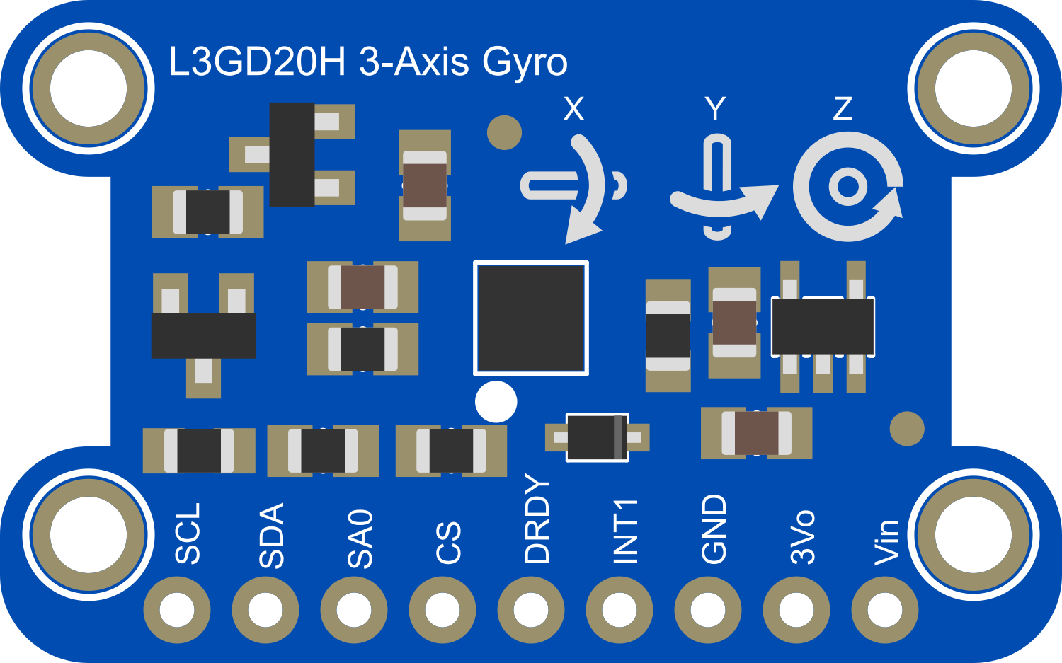
The Adafruit L3GD20H Triple-Axis Gyro Breakout Board is a compact and versatile sensor designed to measure angular velocity along three perpendicular axes: pitch, roll, and yaw. This makes it an ideal component for applications in robotics, motion sensing, and stabilization systems. The board features the L3GD20H gyroscope chip, which provides high-resolution measurements and is capable of detecting rates with a high degree of accuracy.

Explore Projects Built with Adafruit L3GD20H Triple-Axis Gyro Breakout Board

Use Cirkit Designer to design, explore, and prototype these projects online. Some projects support real-time simulation. Click "Open Project" to start designing instantly!
Adafruit MPU6050 and VL6180X Sensor Interface with Servo Control
Image of wire: A project utilizing Adafruit L3GD20H Triple-Axis Gyro Breakout Board in a practical application
This circuit features an Adafruit QT Py microcontroller interfaced with an Adafruit MPU6050 6-axis accelerometer/gyroscope and an Adafruit VL6180X Time of Flight (ToF) distance sensor, both connected via I2C communication. The QT Py also controls a Servomotor SG90, likely for physical actuation based on sensor inputs. The embedded code initializes the sensors, reads their data, and outputs the readings to a serial monitor, with the potential for motion control based on the sensor feedback.
Cirkit Designer LogoOpen Project in Cirkit Designer
ESP32-Based Multi-Sensor Interface with GSM and Display
Image of NAAZ: A project utilizing Adafruit L3GD20H Triple-Axis Gyro Breakout Board in a practical application
This circuit features an ESP32 Devkit V1 microcontroller as its central processing unit, interfacing with a variety of sensors and modules for monitoring and communication purposes. It includes an LCD I2C display for user interface, a SIM800L module for GSM communication, and sensors like the Adafruit L3GD20H gyro, Adafruit ADXL377 accelerometer, DS18B20 temperature sensor, and a pulse sensor for environmental and physiological data collection. The circuit also controls a red and a green LED, each with a current-limiting resistor, and a buzzer for audio feedback, all of which are likely used for status indication or alerts.
Cirkit Designer LogoOpen Project in Cirkit Designer
Teensy 4.1 Based Biometric Data Acquisition System with AD8232 Heart Rate Monitor and LIS3DH Accelerometer
Image of Teensy 4.1 accelerometer: A project utilizing Adafruit L3GD20H Triple-Axis Gyro Breakout Board in a practical application
This circuit integrates a Teensy 4.1 microcontroller with an Adafruit LIS3DH Triple-Axis Accelerometer and an AD8232 Heart Rate Monitor. The accelerometer communicates with the Teensy via I2C (SCL and SDA lines), while the heart rate monitor's output and lead-off detection (LO+ and LO-) are connected to the Teensy's analog inputs. The circuit is designed to measure both acceleration and heart rate signals, likely for a wearable or health monitoring device.
Cirkit Designer LogoOpen Project in Cirkit Designer
Battery-Powered Sensor Hub with Adafruit QT Py RP2040 and OLED Display
Image of 512: A project utilizing Adafruit L3GD20H Triple-Axis Gyro Breakout Board in a practical application
This circuit features an Adafruit QT Py RP2040 microcontroller interfacing with an MPU-6050 accelerometer, an Adafruit APDS-9960 sensor, and a 0.96" OLED display via I2C communication. It is powered by a 3.7V LiPo battery and includes a green LED with a current-limiting resistor connected to an analog pin of the microcontroller.
Cirkit Designer LogoOpen Project in Cirkit Designer

Explore Projects Built with Adafruit L3GD20H Triple-Axis Gyro Breakout Board

Use Cirkit Designer to design, explore, and prototype these projects online. Some projects support real-time simulation. Click "Open Project" to start designing instantly!
Image of wire: A project utilizing Adafruit L3GD20H Triple-Axis Gyro Breakout Board in a practical application
Adafruit MPU6050 and VL6180X Sensor Interface with Servo Control
This circuit features an Adafruit QT Py microcontroller interfaced with an Adafruit MPU6050 6-axis accelerometer/gyroscope and an Adafruit VL6180X Time of Flight (ToF) distance sensor, both connected via I2C communication. The QT Py also controls a Servomotor SG90, likely for physical actuation based on sensor inputs. The embedded code initializes the sensors, reads their data, and outputs the readings to a serial monitor, with the potential for motion control based on the sensor feedback.
Cirkit Designer LogoOpen Project in Cirkit Designer
Image of NAAZ: A project utilizing Adafruit L3GD20H Triple-Axis Gyro Breakout Board in a practical application
ESP32-Based Multi-Sensor Interface with GSM and Display
This circuit features an ESP32 Devkit V1 microcontroller as its central processing unit, interfacing with a variety of sensors and modules for monitoring and communication purposes. It includes an LCD I2C display for user interface, a SIM800L module for GSM communication, and sensors like the Adafruit L3GD20H gyro, Adafruit ADXL377 accelerometer, DS18B20 temperature sensor, and a pulse sensor for environmental and physiological data collection. The circuit also controls a red and a green LED, each with a current-limiting resistor, and a buzzer for audio feedback, all of which are likely used for status indication or alerts.
Cirkit Designer LogoOpen Project in Cirkit Designer
Image of Teensy 4.1 accelerometer: A project utilizing Adafruit L3GD20H Triple-Axis Gyro Breakout Board in a practical application
Teensy 4.1 Based Biometric Data Acquisition System with AD8232 Heart Rate Monitor and LIS3DH Accelerometer
This circuit integrates a Teensy 4.1 microcontroller with an Adafruit LIS3DH Triple-Axis Accelerometer and an AD8232 Heart Rate Monitor. The accelerometer communicates with the Teensy via I2C (SCL and SDA lines), while the heart rate monitor's output and lead-off detection (LO+ and LO-) are connected to the Teensy's analog inputs. The circuit is designed to measure both acceleration and heart rate signals, likely for a wearable or health monitoring device.
Cirkit Designer LogoOpen Project in Cirkit Designer
Image of 512: A project utilizing Adafruit L3GD20H Triple-Axis Gyro Breakout Board in a practical application
Battery-Powered Sensor Hub with Adafruit QT Py RP2040 and OLED Display
This circuit features an Adafruit QT Py RP2040 microcontroller interfacing with an MPU-6050 accelerometer, an Adafruit APDS-9960 sensor, and a 0.96" OLED display via I2C communication. It is powered by a 3.7V LiPo battery and includes a green LED with a current-limiting resistor connected to an analog pin of the microcontroller.
Cirkit Designer LogoOpen Project in Cirkit Designer

Common Applications and Use Cases

  • Inertial Measurement Units (IMUs) for orientation tracking
  • Motion control systems for robotics
  • User input devices (e.g., game controllers, pointing devices)
  • Vehicle navigation systems for dead reckoning
  • Stabilization systems for drones and other RC vehicles

Technical Specifications

Key Technical Details

  • Supply Voltage (VDD): 2.4V to 3.6V
  • Output Data Rates (ODR): 12.5 Hz to 800 Hz
  • Sensitivity: 245/500/2000 dps (degrees per second)
  • Communication Interface: I2C/SPI
  • Operating Temperature Range: -40°C to +85°C

Pin Configuration and Descriptions

Pin Number Name Description
1 VIN Supply voltage (2.4V to 3.6V)
2 GND Ground connection
3 SCL I2C clock line
4 SDA I2C data line
5 SA0 I2C address selection pin
6 CS Chip select for SPI (active low)
7 SDO SPI data output (MISO)
8 SDA/SPI SPI data input (MOSI)
9 SCL/SPC SPI clock

Usage Instructions

How to Use the Component in a Circuit

  1. Powering the Board:

    • Connect the VIN pin to a 2.4V to 3.6V power supply.
    • Connect the GND pin to the ground of your power supply.
  2. I2C Communication:

    • Connect the SCL pin to the I2C clock line of your microcontroller.
    • Connect the SDA pin to the I2C data line of your microcontroller.
    • If using multiple I2C devices, ensure each device has a unique address by setting the SA0 pin accordingly.
  3. SPI Communication (Optional):

    • Connect the SCL/SPC to the SPI clock line of your microcontroller.
    • Connect the SDA/SPI to the SPI MOSI line of your microcontroller.
    • Connect the SDO to the SPI MISO line of your microcontroller.
    • Control the CS pin to enable and disable the device on the SPI bus.

Important Considerations and Best Practices

  • Ensure that the power supply is within the specified voltage range to prevent damage.
  • Use pull-up resistors on the I2C lines if they are not provided by the microcontroller.
  • When using SPI, ensure that the CS pin is only active for the L3GD20H to avoid bus contention.
  • Place the gyro in a location with minimal vibration and temperature fluctuations for best performance.

Example Code for Arduino UNO

#include <Wire.h>
#include <Adafruit_Sensor.h>
#include <Adafruit_L3GD20_U.h>

Adafruit_L3GD20_Unified gyro = Adafruit_L3GD20_Unified(20);

void setup(void) {
  Serial.begin(9600);
  Serial.println("Gyroscope Test"); Serial.println("");
  
  /* Initialize the sensor */
  if(!gyro.begin())
  {
    /* There was a problem detecting the L3GD20 ... check your connections */
    Serial.println("Ooops, no L3GD20 detected ... Check your wiring!");
    while(1);
  }
}

void loop(void) {
  /* Get a new sensor event */
  sensors_event_t event;
  gyro.getEvent(&event);
 
  /* Display the results (angular velocity is measured in degrees per second) */
  Serial.print("X: "); Serial.print(event.gyro.x); Serial.print(" ");
  Serial.print("Y: "); Serial.print(event.gyro.y); Serial.print(" ");
  Serial.print("Z: "); Serial.print(event.gyro.z); Serial.print(" ");
  Serial.println("deg/s");
  
  /* Delay a bit to keep serial output from being too crazy */
  delay(500);
}

This example initializes the L3GD20H sensor and continuously reads the angular velocity in degrees per second from the X, Y, and Z axes, outputting the results to the serial monitor.

Troubleshooting and FAQs

Common Issues Users Might Face

  • Sensor not detected: Ensure that the wiring is correct and that the power supply is within the specified range.
  • Inaccurate readings: Verify that the sensor is placed in a stable environment and recalibrate if necessary.
  • I2C/SPI communication failure: Check the pull-up resistors on the I2C lines or the CS line control for SPI.

Solutions and Tips for Troubleshooting

  • Double-check all connections and solder joints.
  • Use the I2C scanner sketch to confirm the device address.
  • Ensure that the microcontroller libraries are up to date.
  • Consult the Adafruit L3GD20H datasheet for detailed operational characteristics.

FAQs

Q: Can the L3GD20H be used with a 5V microcontroller? A: Yes, but ensure that the VIN pin is connected to a 3.3V supply, and use logic level converters for I2C/SPI lines if necessary.

Q: How can I change the sensitivity of the sensor? A: The sensitivity can be adjusted through software using the provided library functions.

Q: What is the default I2C address of the L3GD20H? A: The default I2C address is 0x6B when SA0 is high and 0x6A when SA0 is low.

Q: How do I calibrate the gyroscope? A: Calibration involves taking multiple readings at a known stationary state and averaging them to determine an offset. This offset is then subtracted from subsequent readings.