How to Use 2.42inch OLED Display Module, 128×64 Resolution, SPI / I2C Communication: Examples, Pinouts, and Specs
Introduction
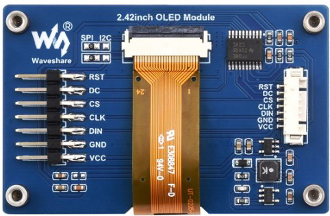
The 2.42inch OLED Display Module by Waveshare is a compact and versatile display solution designed for a wide range of applications. With a resolution of 128×64 pixels, this OLED module delivers crisp and clear visuals, making it ideal for displaying text, graphics, and simple animations. It supports both SPI and I2C communication protocols, ensuring compatibility with various microcontrollers, including Arduino, Raspberry Pi, and STM32.
Explore Projects Built with 2.42inch OLED Display Module, 128×64 Resolution, SPI / I2C Communication


Explore Projects Built with 2.42inch OLED Display Module, 128×64 Resolution, SPI / I2C Communication
Common Applications and Use Cases
- Wearable devices: Compact size and low power consumption make it suitable for smartwatches and fitness trackers.
- IoT projects: Ideal for displaying sensor data or system status in IoT applications.
- Embedded systems: Used in control panels, industrial equipment, and home automation systems.
- Prototyping and education: Perfect for hobbyists and students learning about display modules and microcontroller interfacing.
Technical Specifications
Below are the key technical details of the 2.42inch OLED Display Module:
| Parameter | Value |
|---|---|
| Display Type | OLED |
| Diagonal Size | 2.42 inches |
| Resolution | 128×64 pixels |
| Communication Protocol | SPI / I2C |
| Operating Voltage | 3.3V / 5V |
| Driver IC | SSD1309 |
| Viewing Angle | >160° |
| Display Color | Monochrome (White) |
| Operating Temperature | -40°C to 85°C |
| Dimensions | 60.5mm × 37mm × 5.3mm |
Pin Configuration and Descriptions
The module has a 7-pin interface for SPI communication and an additional pin for I2C selection. Below is the pinout:
| Pin | Name | Description |
|---|---|---|
| 1 | GND | Ground pin, connect to the ground of the power supply. |
| 2 | VCC | Power supply pin, supports 3.3V or 5V. |
| 3 | D0 (SCL) | Clock line for SPI (D0) or I2C (SCL). |
| 4 | D1 (SDA) | Data line for SPI (D1) or I2C (SDA). |
| 5 | RES | Reset pin, used to reset the display module. |
| 6 | DC | Data/Command control pin. High for data, low for command. |
| 7 | CS | Chip Select pin, used to enable the module in SPI mode. |
| 8 | BS0 | Communication mode selection. Connect to GND for SPI or VCC for I2C. |
Usage Instructions
How to Use the Component in a Circuit
- Power Supply: Connect the VCC pin to a 3.3V or 5V power source and the GND pin to ground.
- Communication Mode:
- For SPI mode, connect the BS0 pin to GND.
- For I2C mode, connect the BS0 pin to VCC.
- SPI Connections:
- Connect the D0 (SCL) pin to the SPI clock pin of your microcontroller.
- Connect the D1 (SDA) pin to the SPI data pin.
- Use the CS pin to enable the module and the DC pin to toggle between data and command modes.
- I2C Connections:
- Connect the D0 (SCL) pin to the I2C clock pin of your microcontroller.
- Connect the D1 (SDA) pin to the I2C data pin.
- Reset Pin: Connect the RES pin to a GPIO pin on your microcontroller for resetting the display.
Important Considerations and Best Practices
- Voltage Compatibility: Ensure the power supply voltage matches the module's requirements (3.3V or 5V).
- Pull-up Resistors: For I2C communication, use pull-up resistors (typically 4.7kΩ) on the SCL and SDA lines.
- Initialization: Always initialize the display using the appropriate library or driver before sending data.
- Avoid Static Damage: Handle the module carefully to prevent damage from electrostatic discharge (ESD).
Example Code for Arduino UNO (SPI Mode)
Below is an example of how to use the module with an Arduino UNO in SPI mode. The code uses the popular Adafruit SSD1306 library.
#include <Adafruit_GFX.h>    // Core graphics library
#include <Adafruit_SSD1306.h> // SSD1306 driver library

#define SCREEN_WIDTH 128 // OLED display width, in pixels
#define SCREEN_HEIGHT 64 // OLED display height, in pixels

// Declaration for SSD1306 display connected using SPI
#define OLED_MOSI   11  // Data pin (D1)
#define OLED_CLK    13  // Clock pin (D0)
#define OLED_DC     9   // Data/Command pin
#define OLED_CS     10  // Chip Select pin
#define OLED_RESET  8   // Reset pin

Adafruit_SSD1306 display(SCREEN_WIDTH, SCREEN_HEIGHT,
                         OLED_MOSI, OLED_CLK, OLED_DC,
                         OLED_RESET, OLED_CS);

void setup() {
  // Initialize the display
  if (!display.begin(SSD1306_SWITCHCAPVCC)) {
    Serial.println(F("SSD1306 allocation failed"));
    for (;;); // Don't proceed, loop forever
  }

  display.clearDisplay(); // Clear the buffer
  display.setTextSize(1); // Set text size to 1
  display.setTextColor(SSD1306_WHITE); // Set text color to white
  display.setCursor(0, 0); // Set cursor to top-left corner
  display.println(F("Hello, OLED!")); // Print text
  display.display(); // Display the text
}

void loop() {
  // Nothing to do here
}
Troubleshooting and FAQs
Common Issues and Solutions
Display Not Turning On:
- Verify the power supply connections (VCC and GND).
- Check if the communication mode (SPI/I2C) is correctly configured.
- Ensure the reset pin (RES) is properly connected and initialized.
No Output on the Display:
- Confirm that the correct library (e.g., Adafruit SSD1306) is installed and used.
- Double-check the wiring, especially the data and clock lines.
- Ensure the display is initialized in the code before sending data.
Flickering or Unstable Display:
- Check for loose connections or poor soldering.
- Ensure the power supply is stable and within the specified voltage range.
I2C Communication Not Working:
- Verify the pull-up resistors on the SCL and SDA lines.
- Check the I2C address of the module (default is usually 0x3C or 0x3D).
FAQs
Can this module be powered directly from a 5V Arduino pin? Yes, the module supports both 3.3V and 5V power supplies.
What is the default I2C address of the module? The default I2C address is typically 0x3C, but refer to the datasheet for confirmation.
Can I use this module with a Raspberry Pi? Yes, the module is compatible with Raspberry Pi via SPI or I2C communication.
Is the display sunlight-readable? While the OLED display offers high contrast, it is not optimized for direct sunlight readability.