How to Use LM4128-2.5VREF: Examples, Pinouts, and Specs
Introduction
The LM4128-2.5VREF is a precision, low-dropout voltage reference that provides a fixed 2.5V output with high stability and low temperature coefficient. This component is ideal for providing a stable reference voltage in a variety of applications, including analog-to-digital converters (ADCs), digital-to-analog converters (DACs), power supplies, and battery-operated devices.
Explore Projects Built with LM4128-2.5VREF


Explore Projects Built with LM4128-2.5VREF
Common Applications
- Precision voltage reference for ADCs and DACs
- Portable instrumentation
- Power supply monitoring
- Battery-powered devices
Technical Specifications
The LM4128-2.5VREF offers excellent performance characteristics suitable for critical applications. Below are the key technical specifications:
| Parameter | Value |
|---|---|
| Output Voltage | 2.5V |
| Initial Accuracy | ±0.1% |
| Temperature Coefficient | 50 ppm/°C (max) |
| Load Regulation | 60 ppm/mA |
| Line Regulation | 20 ppm/V |
| Output Current Capability | 5 mA to 20 mA |
| Operating Temperature Range | -40°C to +125°C |
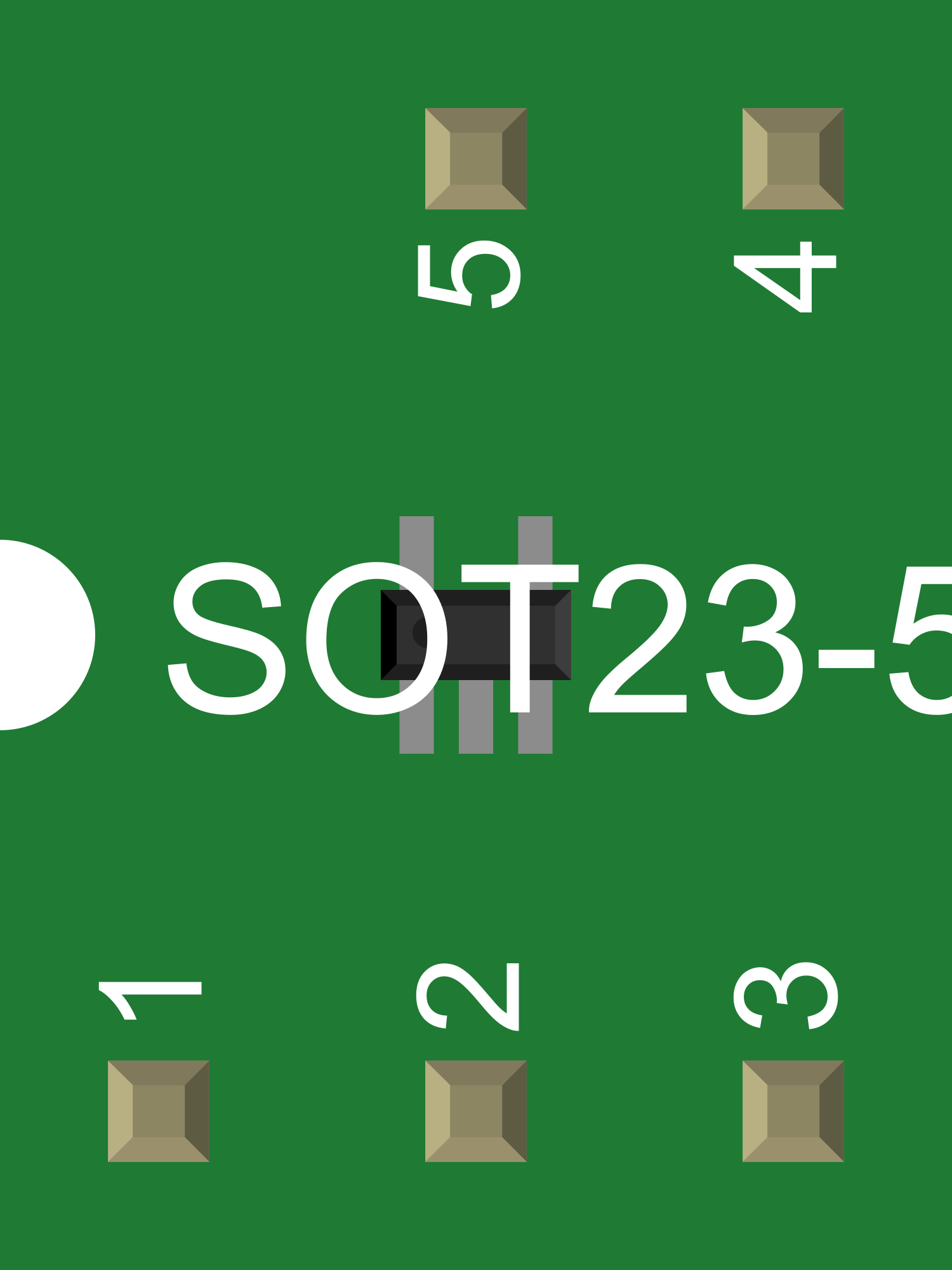
| Package Type | SOT-23, TO-92 |
Pin Configuration and Descriptions
| Pin Number | Name | Description |
|---|---|---|
| 1 | VOUT | Output voltage pin, provides the 2.5V reference |
| 2 | GND | Ground reference for the device |
| 3 | VIN | Input voltage pin, supply voltage for the device |
Usage Instructions
Integration into a Circuit
To use the LM4128-2.5VREF in a circuit, connect the VIN pin to a supply voltage that is at least 1V higher than the desired output voltage to ensure proper operation. The VOUT pin should be connected to the point in the circuit where a stable reference voltage is needed. The GND pin must be connected to the system ground.
Best Practices
- Bypass the VIN pin with a 1µF ceramic capacitor placed as close as possible to the device pins to minimize noise.
- Avoid running high-current traces or noisy signal lines near the device to prevent interference.
- Ensure that the input voltage does not exceed the maximum specified limit to prevent damage to the device.
- Use proper ESD precautions when handling the device to avoid electrostatic damage.
Troubleshooting and FAQs
Common Issues
- Output Voltage Fluctuation: Ensure that the input voltage is stable and that there is adequate bypass capacitance at the VIN pin.
- Device Heating: Check that the output current does not exceed the maximum rating of the device.
FAQs
Q: Can the LM4128-2.5VREF be used with an Arduino UNO? A: Yes, it can be used to provide a stable reference voltage for analog readings with an Arduino UNO.
Q: What is the maximum input voltage for the LM4128-2.5VREF? A: The maximum input voltage is typically 12V, but always refer to the latest datasheet for the specific device limits.
Q: How can I improve the accuracy of my voltage reference in a high-temperature environment? A: Use a voltage reference with a low temperature coefficient and place it in a location with minimal temperature variation.
Example Arduino UNO Code
Below is an example of how to use the LM4128-2.5VREF with an Arduino UNO to take precise analog readings.
// Define the analog pin connected to the voltage reference
const int analogPin = A0;

void setup() {
  // Start the serial communication
  Serial.begin(9600);

  // Configure the analog reference to EXTERNAL
  analogReference(EXTERNAL);
}

void loop() {
  // Read the voltage on the analog pin
  int sensorValue = analogRead(analogPin);

  // Convert the reading to voltage
  float voltage = sensorValue * (2.5 / 1023.0);

  // Print the voltage to the Serial Monitor
  Serial.println(voltage);

  // Wait for a bit before reading again
  delay(1000);
}
Note: Before uploading the code, connect the VOUT pin of the LM4128-2.5VREF to the AREF pin on the Arduino UNO and ensure that the GND pin is connected to the Arduino's ground.
This documentation provides a comprehensive overview of the LM4128-2.5VREF voltage reference. For more detailed information, always refer to the manufacturer's datasheet.