
How to Use 6Kw INVERTER: Examples, Pinouts, and Specs
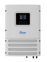
 Design with 6Kw INVERTER in Cirkit Designer
Introduction
A 6kW inverter is an electrical device designed to convert direct current (DC) from sources such as solar panels or batteries into alternating current (AC). This AC power can then be used to operate household appliances, industrial equipment, or even fed back into the electrical grid. The 6kW rating indicates the maximum power output capacity of the inverter, making it suitable for medium to large-scale energy systems.
Explore Projects Built with 6Kw INVERTER
 Open Project in Cirkit Designer
 Open Project in Cirkit Designer
 Open Project in Cirkit Designer
 Open Project in Cirkit Designer
Explore Projects Built with 6Kw INVERTER
Open Project in Cirkit DesignerOpen Project in Cirkit DesignerOpen Project in Cirkit DesignerOpen Project in Cirkit DesignerCommon Applications and Use Cases
- Solar power systems for residential or commercial use
- Backup power systems using battery storage
- Grid-tied or off-grid renewable energy systems
- Industrial equipment requiring AC power
- Hybrid energy systems combining solar, wind, and battery storage
Technical Specifications
Key Technical Details
| Parameter | Specification |
|---|---|
| Rated Power Output | 6,000 Watts (6kW) |
| Input Voltage Range (DC) | 48V to 60V |
| Output Voltage (AC) | 230V ± 5% (single-phase) or 400V (three-phase) |
| Output Frequency | 50Hz / 60Hz (selectable) |
| Efficiency | Up to 95% |
| Waveform | Pure Sine Wave |
| Operating Temperature | -10°C to 50°C |
| Cooling Method | Forced air cooling |
| Protection Features | Overload, short circuit, over-temperature, low/high voltage |
Pin Configuration and Descriptions
The 6kW inverter typically has the following input/output terminals:
DC Input Terminals
| Pin Name | Description |
|---|---|
| + (Positive) | Connect to the positive terminal of the DC source (e.g., battery or solar panel). |
| - (Negative) | Connect to the negative terminal of the DC source. |
AC Output Terminals
| Pin Name | Description |
|---|---|
| L (Live) | Live wire for AC output. Connect to the load or grid. |
| N (Neutral) | Neutral wire for AC output. Connect to the load or grid. |
| GND (Ground) | Ground connection for safety. |
Communication Ports (if applicable)
| Port Name | Description |
|---|---|
| RS485 | For monitoring and control via external devices. |
| CAN Bus | Communication with battery management systems (BMS). |
| USB | Firmware updates or data logging. |
Usage Instructions
How to Use the 6kW Inverter in a Circuit
Connect the DC Input:
- Ensure the DC source (e.g., battery or solar panel) matches the inverter's input voltage range (48V to 60V).
- Connect the positive and negative terminals of the DC source to the corresponding DC input terminals on the inverter.
Connect the AC Output:
- For single-phase systems, connect the live (L), neutral (N), and ground (GND) terminals to the load or grid.
- For three-phase systems, follow the manufacturer's wiring diagram to connect the three-phase output.
Power On the Inverter:
- Turn on the inverter using the power switch or control panel.
- Verify that the inverter's status indicators (e.g., LEDs or display) show normal operation.
Monitor and Control:
- Use the communication ports (e.g., RS485 or CAN Bus) to monitor performance or integrate with a battery management system (BMS).
Important Considerations and Best Practices
- Sizing: Ensure the total load connected to the inverter does not exceed 6kW.
- Cooling: Install the inverter in a well-ventilated area to prevent overheating.
- Grounding: Properly ground the inverter to ensure safety and compliance with electrical codes.
- Battery Compatibility: If using batteries, ensure they are compatible with the inverter's voltage and current requirements.
- Firmware Updates: Regularly check for firmware updates to improve performance and add new features.
Arduino UNO Integration (Example for Monitoring)
If the inverter supports RS485 communication, you can use an Arduino UNO to monitor its status. Below is an example code snippet for reading data from the inverter:
#include <ModbusMaster.h> // Include Modbus library for RS485 communication

ModbusMaster inverter; // Create ModbusMaster object

void setup() {
  Serial.begin(9600); // Initialize serial communication for debugging
  inverter.begin(1, Serial); // Set Modbus ID to 1 and use Serial for communication

  // Initialize RS485 communication
  pinMode(2, OUTPUT); // Set pin 2 as DE/RE control for RS485 module
  digitalWrite(2, LOW); // Set to receive mode
}

void loop() {
  uint8_t result;
  uint16_t data;

  // Read inverter status register (example register address: 0x0001)
  result = inverter.readHoldingRegisters(0x0001, 1);

  if (result == inverter.ku8MBSuccess) {
    data = inverter.getResponseBuffer(0); // Get the data from the response buffer
    Serial.print("Inverter Status: ");
    Serial.println(data); // Print the status to the serial monitor
  } else {
    Serial.println("Failed to read inverter status."); // Print error message
  }

  delay(1000); // Wait 1 second before the next read
}
Note: Ensure you connect the RS485 module to the Arduino UNO correctly. Use pins RX (0) and TX (1) for communication, and connect the DE/RE pin to a digital pin (e.g., pin 2).
Troubleshooting and FAQs
Common Issues and Solutions
| Issue | Possible Cause | Solution |
|---|---|---|
| Inverter does not power on | DC input voltage is too low or too high | Check the DC source voltage and ensure it is within the specified range. |
| Overload protection triggered | Load exceeds 6kW | Reduce the load to within the inverter's capacity. |
| Overheating | Poor ventilation or high ambient temperature | Ensure proper airflow and install the inverter in a cooler location. |
| No AC output | Incorrect wiring or faulty connections | Verify all connections and ensure proper wiring. |
| Communication failure (RS485) | Incorrect baud rate or wiring | Check the communication settings and wiring connections. |
FAQs
Can I use this inverter with a 24V battery system?
- No, the inverter requires a DC input voltage range of 48V to 60V. A 24V system is incompatible.
Is this inverter suitable for off-grid systems?
- Yes, the inverter can be used in both off-grid and grid-tied systems, depending on the configuration.
What type of waveform does the inverter produce?
- The inverter produces a pure sine wave, which is ideal for sensitive electronic devices.
How do I update the inverter's firmware?
- Use the USB port to connect the inverter to a computer and follow the manufacturer's firmware update instructions.
Can I connect this inverter directly to the grid?
- Yes, but ensure compliance with local regulations and use appropriate safety measures.
By following this documentation, users can effectively integrate and operate a 6kW inverter in their energy systems.