How to Use Adafruit Pi Cobbler: Examples, Pinouts, and Specs
Introduction
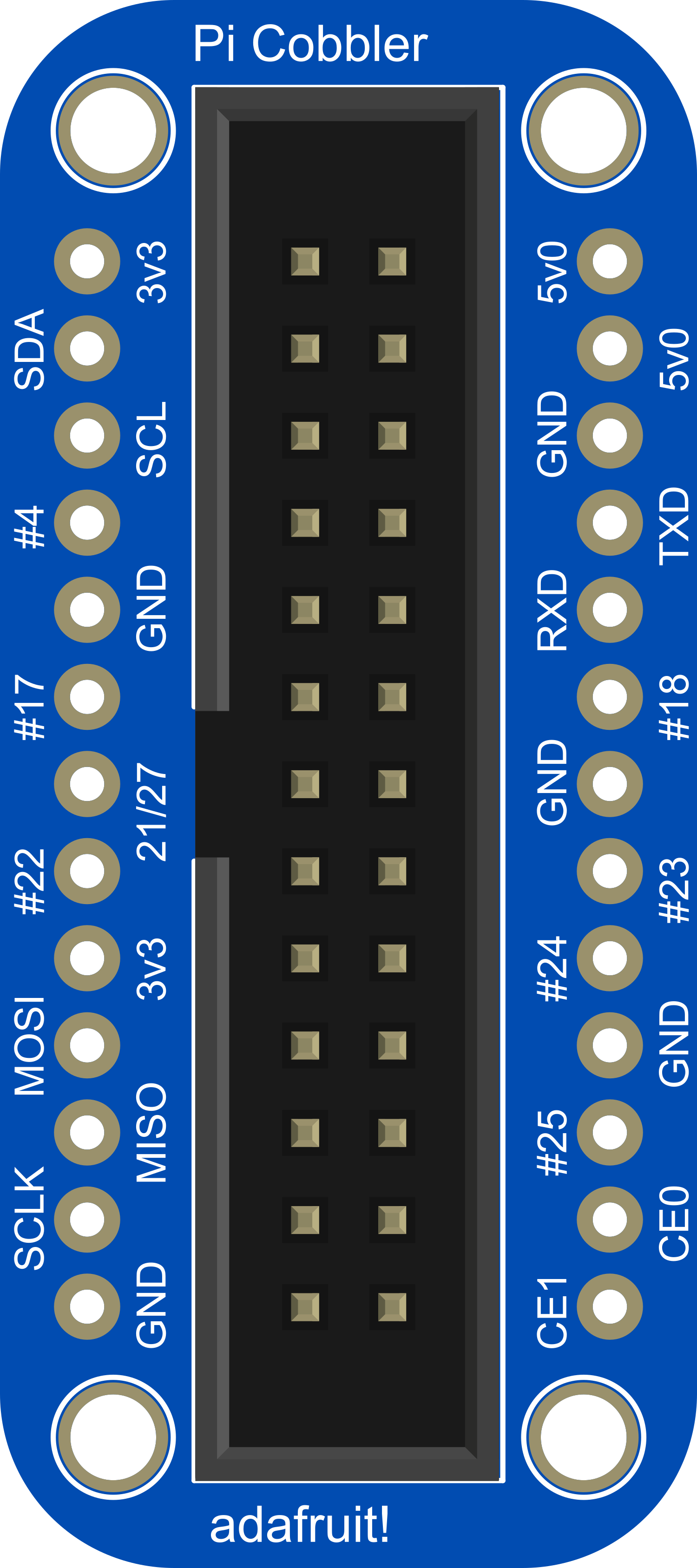
The Adafruit Pi Cobbler is a breakout board designed to facilitate the use of the GPIO (General Purpose Input/Output) pins from a Raspberry Pi on a breadboard. This component is essential for hobbyists, educators, and professionals who wish to prototype circuits and create physical computing projects with ease. The Pi Cobbler is compatible with all Raspberry Pi models that have the 40-pin GPIO connector.
Explore Projects Built with Adafruit Pi Cobbler
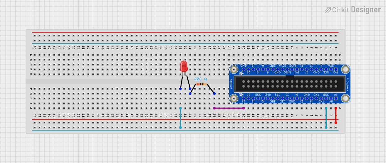


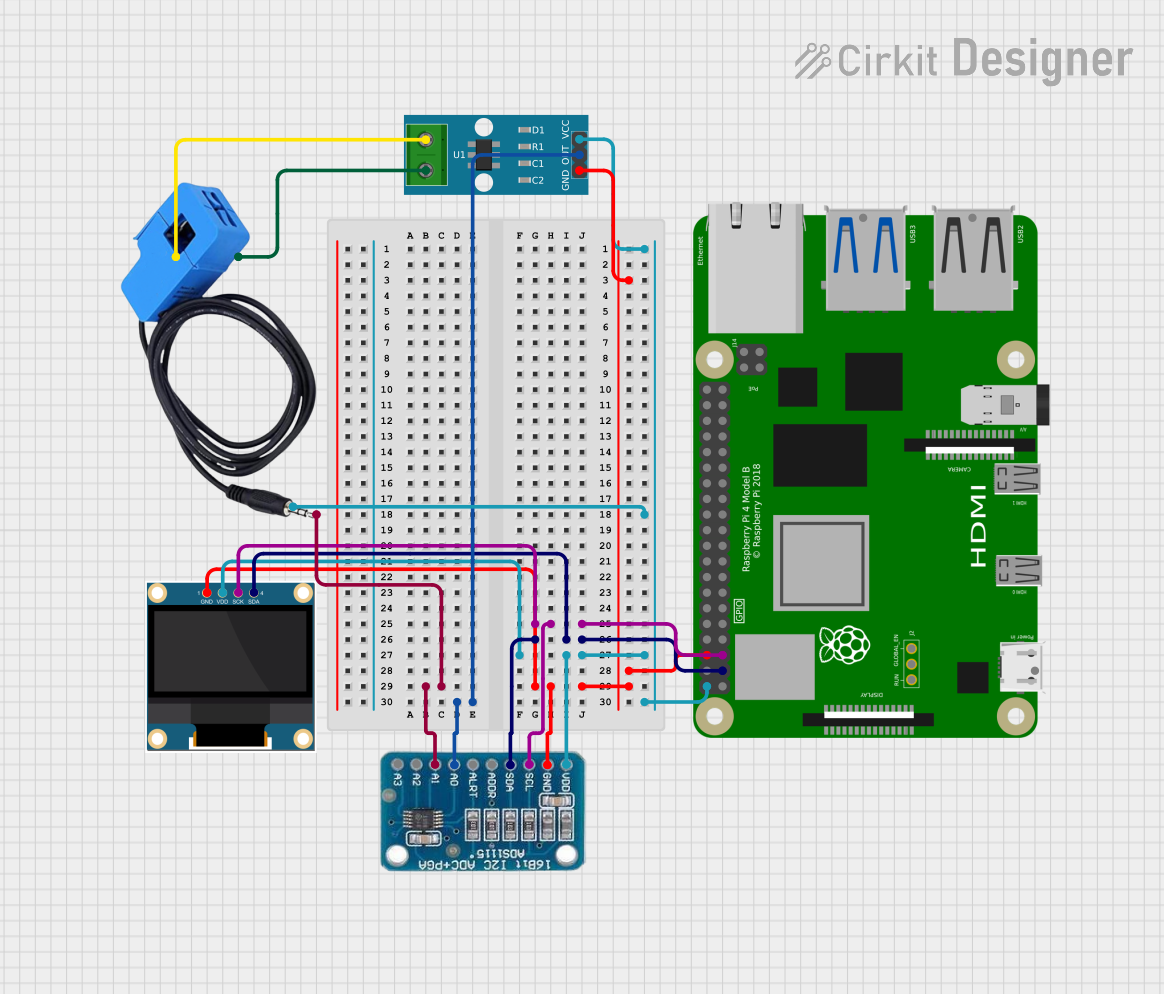
Explore Projects Built with Adafruit Pi Cobbler
Common Applications and Use Cases
- Prototyping Raspberry Pi circuits
- Educational projects in electronics and computer science
- Interfacing Raspberry Pi with sensors, LEDs, motors, and other electronic components
- Developing physical computing applications
- Rapid testing of Raspberry Pi GPIO functionality
Technical Specifications
Key Technical Details
- Compatibility: Raspberry Pi with 40-pin GPIO connector
- Connector Type: 40-pin IDC socket to connect with the Raspberry Pi
- Breadboard Connection: THT (Through-Hole Technology) pins for breadboard insertion
- Dimensions: Varies by version, typically around 75mm x 20mm x 11mm
Pin Configuration and Descriptions
The following table outlines the pin configuration of the Adafruit Pi Cobbler when connected to a Raspberry Pi with a 40-pin GPIO header.
| Pin Number | Name | Description |
|---|---|---|
| 1 | 3V3 | 3.3V Power Rail |
| 2 | 5V | 5V Power Rail |
| 3 | SDA | I2C Data |
| 4 | 5V | 5V Power Rail |
| 5 | SCL | I2C Clock |
| 6 | GND | Ground |
| ... | ... | ... |
| 39 | GND | Ground |
| 40 | GPIO21 | General Purpose I/O |
Note: The table above is a partial representation. The full pinout should be consulted for complete details.
Usage Instructions
How to Use the Component in a Circuit
Connect the Pi Cobbler to the Raspberry Pi:
- Ensure the Raspberry Pi is powered off.
- Align the 40-pin IDC cable with the GPIO pins on the Raspberry Pi and the Pi Cobbler, then press gently to connect.
Insert the Pi Cobbler into a Breadboard:
- Place the THT pins of the Pi Cobbler into the breadboard, ensuring a secure and stable connection.
Wire Components to the Breadboard:
- Use jumper wires to connect other components to the breadboard, interfacing with the Pi Cobbler pins as needed.
Power On the Raspberry Pi:
- Once all connections are double-checked, power on the Raspberry Pi to begin using the GPIO pins through the Pi Cobbler.
Important Considerations and Best Practices
- Avoid Hot-Swapping: Do not connect or disconnect the Pi Cobbler while the Raspberry Pi is powered on to prevent damage.
- Check Pin Alignment: Ensure the IDC cable is correctly aligned to avoid incorrect connections.
- Use Pull-Up/Pull-Down Resistors: When interfacing with digital inputs, use appropriate resistors to avoid floating pins.
- Voltage Levels: Be mindful of the voltage levels; the Raspberry Pi GPIO pins operate at 3.3V logic levels.
Troubleshooting and FAQs
Common Issues Users Might Face
- Loose Connections: Ensure that all connections are secure if the circuit is not functioning as expected.
- Incorrect Wiring: Double-check the wiring against the pinout to ensure accuracy.
- Damaged GPIO Pins: If a GPIO pin is not responding, it may be damaged. Try using another pin if possible.
Solutions and Tips for Troubleshooting
- Visual Inspection: Perform a thorough visual inspection of all connections and components for any obvious issues.
- Use a Multimeter: Check for continuity and correct voltages with a multimeter.
- Consult the Raspberry Pi Pinout: Refer to the official Raspberry Pi GPIO pinout documentation for guidance.
FAQs
Q: Can the Pi Cobbler be used with all versions of the Raspberry Pi? A: The Pi Cobbler is compatible with Raspberry Pi models that have the 40-pin GPIO connector.
Q: Do I need to install any drivers to use the Pi Cobbler? A: No, the Pi Cobbler does not require drivers. It is a passive component that simply extends the GPIO pins to a breadboard.
Q: Can I use the Pi Cobbler with a Raspberry Pi Zero? A: Yes, the Raspberry Pi Zero has a 40-pin GPIO header compatible with the Pi Cobbler.
Q: How do I know if my Pi Cobbler is connected correctly? A: Ensure the IDC cable's red stripe aligns with pin 1 on both the Raspberry Pi and the Pi Cobbler. This usually corresponds to the 3V3 power pin.
Note: This documentation is provided for informational purposes and does not constitute a warranty of any kind. Users should exercise caution and adhere to safety standards when working with electronic components.